2 Section 61150087L1-5, Issue 1 61150.087L1-5A
for access during maintenance. Note clearances
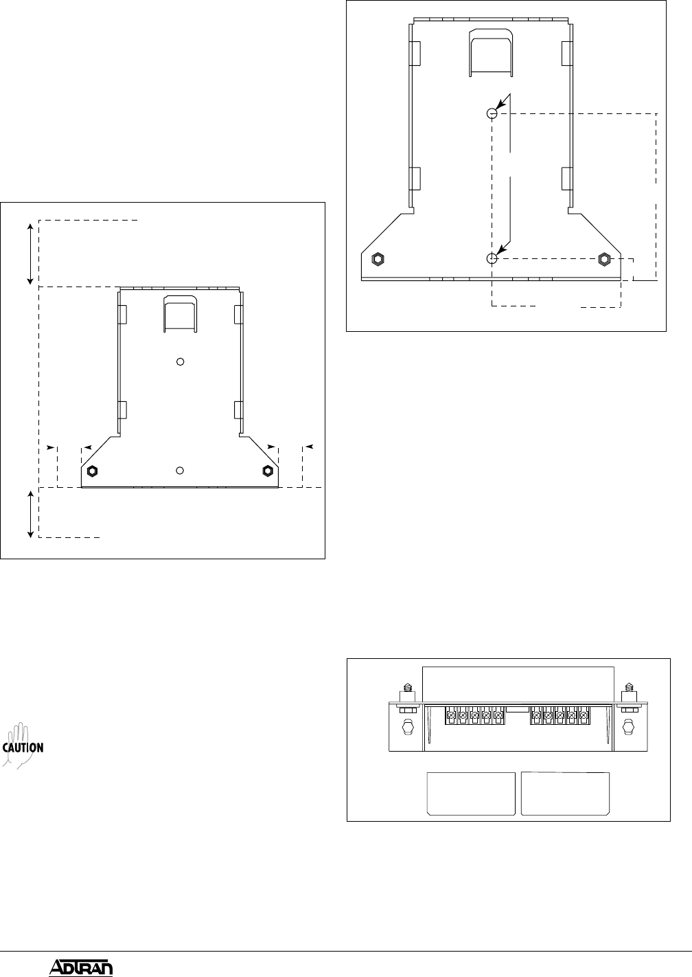
required for removing the Environmental Housing.
See Figure 2 for mounting clearances.
2. Place the mounting bracket 3/4" spacers between
the rear of the mounting bracket and the mounting
surface. The spacers are required to insure the
mounting bracket is not warped during installation
or use.
3. Insert the 1/4" x 1
1/2
" Hex head lag screws through
the mounting holes of the mounting bracket and
spacers. Tighten securely with a 7/16" nut driver.
Figure 2. Clearances
9.0"
8.5"
6.0"
1.0"
1.0"
Install the T400 Environmental Housing
1. Fasten the Environmental Housing to the mounting
bracket using the two mounting bracket bolts.
2. Tighten the two bolts using a
7
/
16
" nut driver to
25 in-lbs.
Power Modules in the central office should be
removed or de-energized prior to installation
and maintenance of the T400 Single
Environmental Housing. Appropriate Methods
and Procedures should be followed to insure
personal safety.
Network Wiring
1. Remove the network cover on the base using a
7
/16" nut driver.
2. Connect the wiring in the terminal blocks as shown
in Table A. The terminal block will accommodate
a #6 Spade Lug.
4 "
3/4
"
5 "
3/16
3/8
Mounting
Holes
Figure 3. Mounting Holes
3. Connect the ground cable to an appropriate
ground. (Surge arrestors work only when the
ground cable is connected.)
4. Replace the network cover on the base using a
7
/16" nut driver. Tighten to 20 in-lbs.
Customer Wiring
1. Remove the customer cover on the base using a
flat-head screwdriver.
2. Connect the wiring in the terminal blocks as shown
in Table A. The terminal block will accommodate
a #6 Spade Lug. The terminal blocks are shown
in Figure 4.
3. Replace the customer cover on the base using a
flat-head screwdriver.
CUSTOMER ACCESS
NETWORK INTERFACE DEVICE
WARNING!
COVER TO BE
REMOVED BY TELEPHONE
COMPANY PERSONNEL
ONLY
5 15 49 55 NC
7 13 41 47 11
Remove the Environmental Housing Cover
1. Wipe any debris from the cover and base.
2. Remove the two housing cover bolts using a
7
/
16
"
nut driver.
Figure 4. Wiring Terminals


