7/9/2008
RS-603 REV A.
10
+12V
Master Door
Lock Switch
X
X
Splice
Splice
Cut the Existing
Lock Wire
To Door
Lock Motors
Cut the Existing
Unlock Wire
3 Pin Plug
To Alarm
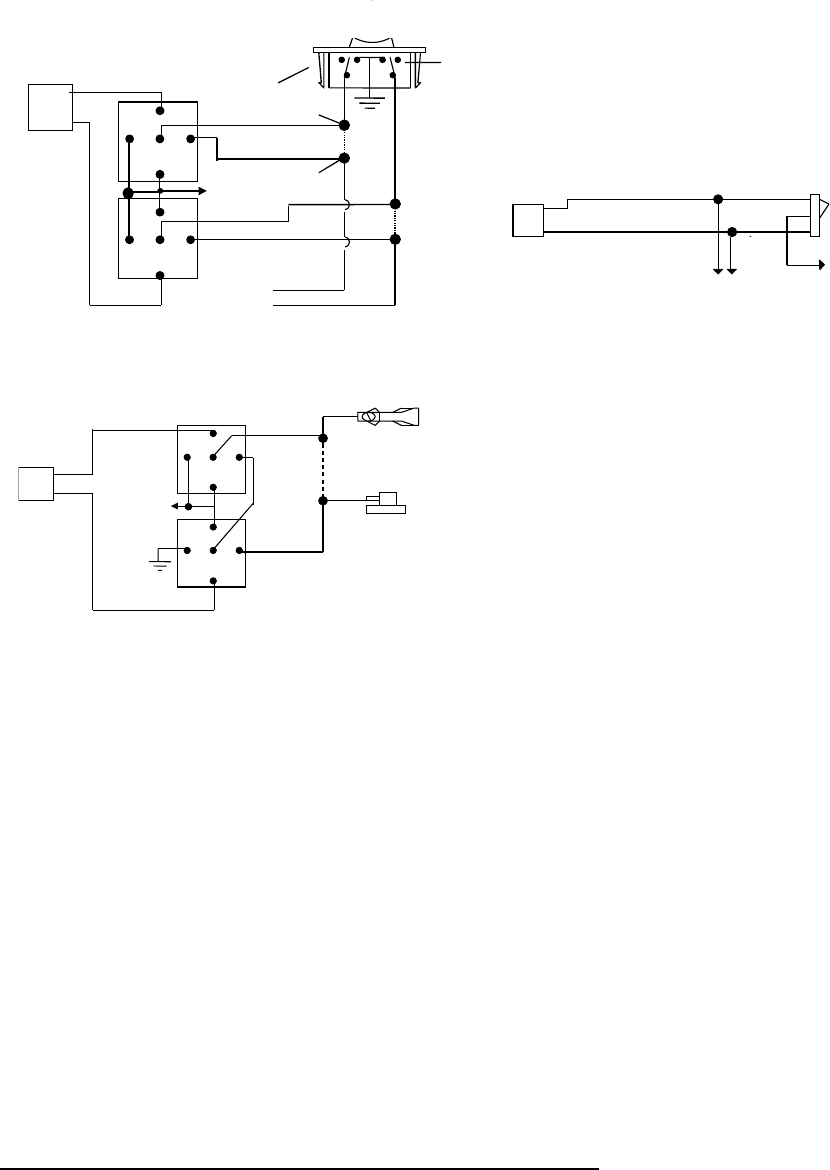
5-WIRE ALTERNATING DOOR LOCK
30
86
87a
85
87
30
86
87a
85
87
+12V
Green Wire
Blue Wire
POSITIVE TRIGGER DOOR LOCK SYSTEM
Blue Wire Door lock
Green Wire Door Unlock
Locking
Master
Switch
To Exiting
Door Lock Relay
+ 12V
VACUUM OPERATED CENTROL LOCKING
Green Wire
Blue Wire
+12V
X
Cut
Compressor
Door Switch
30
86
87a
85
87
30
86
87a
85
87
3 Pin
Plug To
larm
VACUUM OPERATED DOOR LOCKING SYSTEM:
TYPICAL OF MERCEDES BENZ AND AUDI.
Locate the wire under the driver's kick panel. Use the
voltmeter connecting to ground, verify that you have t
correct wire with the doors unlocked, the voltmeter will
receive "12 volts". Lock the doors and the voltmeter wi
read "0 volt". Move the alligator clip to +12V and the
voltmeter will receive "12 volts". Cut this wire and mak
connections. Be sure to program door lock timer to
3.5 seconds.(See Alarn Feature
II – 5 Programming.)
H7 Flashing LED. Connect to LED Plug
H8. RS232 C3 SERIAL TWO-WAY DATA PORT CONNECTION:
This connector is to be used for Serial Data communications with I-Datalink modules by Auto Page only!
DO NOT CONNECT THIS TO ANY OTHER WIRING!
This connector will transmit digital codes to operate all functions of Autopage data modules. When these modules are used, no other
data bus connections need to be made to the RS-603. The Data Bus module will receive its commands directly from the CPU of the
RS-603. This will provide greater theft protection as well as aid in the installation of this product. The RS-232 serial harness is
provided with all Autopage serial data modules and is not included with the RS-603. This two-way data port has been designed for use
with all C I 3 compatible components. C3 Telematics system is available at any authorized Autopage dealer.
This port will only operate correctly with Autopage C3 I-Datalink Modules.


