2. screw holes (6)
3. expansion-card riser
4. screws (6)
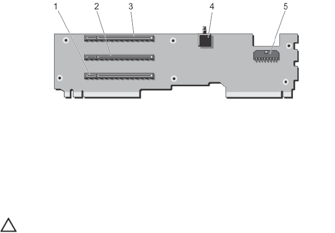
Figure 49. Expansion-card Riser Connectors
1. expansion-card connector (SLOT3)
2. expansion-card connector (SLOT2)
3. expansion-card connector (SLOT1)
4. chassis intrusion switch
5. power cable connector
Installing The Expansion Card Riser
CAUTION: Many repairs may only be done by a certified service technician. You should only perform
troubleshooting and simple repairs as authorized in your product documentation, or as directed by the online or
telephone service and support team. Damage due to servicing that is not authorized by Dell is not covered by your
warranty. Read and follow the safety instructions that came with the product.
1. Align the expansion-card riser with the PCIe cage and slide the riser into the cage, until properly seated.
When properly aligned, the chassis intrusion switch on the riser aligns with the slot on the PCIe cage.
2. Attach the screws to secure the expansion-card to the PCIe cage.
3. Reconnect the power cable.
4. Reinstall the full-height expansion-card divider unit.
5. If applicable, reinstall the expansion card(s) into the expansion-card riser.
6. Reinstall the PCIe cage.
7. Reinstall the cooling-fan assembly.
8. Reinstall the cooling shroud.
9. Close the PCIe cage door.
10. Close the system.
11. If applicable, place the system upright on a flat, stable surface and rotate the system feet outward.
12. Reconnect the enclosure to its electrical outlet and turn the enclosure on, including any attached peripherals.
13. Turn on the server modules using the operating system commands or the CMC.
14. If applicable, install the front bezel.
Integrated Storage Controller Card
Your system includes two dedicated expansion-card slots on the system board for up to two integrated controller cards
that provide the integrated storage subsystem for your system’s internal hard drives.
83


