9
Dealer Motor Assembly Replacement Instructions
1. Accessing the motor assembly
a. Turn the unit off and unplug it from any electrical source before opening
the cabinet.
b. Remove the safety screw(s) from the motor section access panel.
c. Lift the door off the unit.
2. Removing the old motor assembly
a. Disconnect all four motor wires from switch, ground post and capacitor.
b. Disconnect the two white wires from the capacitor.
c. Separate the motor from the motor mount by removing the four screws
found in figure 1.
d. Slide the motor out from under the motor mount to remove it from the unit.
3. Installing the new motor assembly
a. Slide the new motor into the motor mount making sure that the wires
go through the smaller hole offset from the center of the bracket.
b. Secure the new motor to the motor mount with the
four screws removed in step 2c.
c. Connect the wires as follows:
- Black wire from the Plug and Cable (P12) to Line (P3) on the CM71
Power Module
- Green wire from CM71 Power Module to the ground post
- Blue wire from motor to the Motor-2 (P4) post on the CM71 Power
Module
- Yellow/green wire from motor to the ground post
- Brown wire from the motor to a Capacitor (C10) post
- Black wire from the motor to the Motor-1 (P2) post on the CM71
Power Module
- White wire from Neutral (P1) on the CM71 Power Module to the black
wire on the motor via piggyback post to the empty Capacitor (C10)
post.
4. Closing the unit
a. Replace the motor section access panel and secure it with the
screws removed in step 1b.
b. Plug the unit into it’s electrical source and turn it on.
Risk of Sharp Edges Hazard.
Equipment sharp edges can cause injuries.
Avoid grasping equipment edges without protective
gloves.
!
CAUTION
Electrical Shock Hazard.
Can cause injury or death.
Disconnect all electrical power supplies
before servicing.
Do not operate equipment without
access panels in place.
!
WARNING
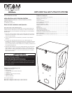
Electrical diagram
Figure 1