Figure 4
U.L. Model No.: CF3300
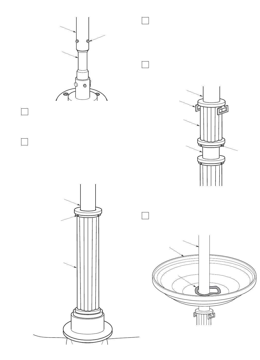
5. Route the motor lead wires and support wire
through the decorative downrod sleeve assembly.
Carefully slide the decorative downrod sleeve
assembly over the downrod and set firmly on
downrod coupling (Figure 3).
6. Using the hex wrench (supplied), tighten the three
setscrews located at the top of the decorative
downrod sleeve assembly (Figure 3).
NOTE: It is important that all setscrews are
securely tightened and the decorative downrod
sleeve assembly is secure. To not overtighten
setscrews.
7. Route the motor lead wires and support wire
through the upper decorative downrod sleeve and
the decorative strap ring (Figure 4). Careful not to
scratch the downrod with the sleeve and ring
during installation.
NOTE: Be careful not to scratch the downrod
during installation.
8. Position the upper decorative downrod sleeve and
the decorative strap ring just above the decorative
downrod sleeve assembly during initial installation
(Figure 4).
Figure 5
NOTE: Apply masking tape to the entire edge of
the ceiling canopy center hole to prevent
accidental scratching of downrod surface
(Figure 5).
9. Route the motor lead wires and support wire
through the ceiling canopy (Figure 5). Use extreme
caution not to scratch the downrod with the ceiling
canopy during installation.
NOTE: Be careful not to scratch the downrod
during installation.