3-7
Fiber Matrix 6400 Switcher • Operation
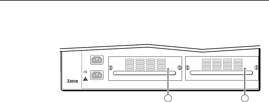
Rear Panel Power Indicators
The two power supply modules (primary power supply and redundant power
supply, figure 3-3) each have a 2-color LED.
ANAHEIM, CA
100-240V 50/60Hz
2A MAX.
100-240V 50/60Hz
2A MAX.
REDUNDANT
PRIMARY
PRIMARY POWER SUPPLY REDUNDANT POWER SUPPLY
1 1
Figure 3-3 — Rear panel power supply indicators
a
Primary and Redundant Power Supply LEDs —
Green — Indicates that the associated power supply is operating within
normal tolerances.
Red — Indicates that the associated power supply has failed. See chapter 7,
“Maintenance and Modifications”, to replace the power supply.
Front Panel Operations
The following paragraphs detail the power-up process and then provide sample
procedures for the following actions:
• Creatingties,setsofties,andcongurations
• Changingaconguration
• Viewingties,setsofties,andcongurations
• CreatingI/Ogroups
• Savingapreset
• Recallingapreset
• Mutingandunmutingoutputs
• Lockingandunlockingthefrontpanel
• Performingfrontpanelresets
• ReadingandsettingtheRS-232/RS-422Remoteportsettings


