FOX 500 DA6 • Remote Control
Remote Control
FOX 500 DA6 • Remote Control
The DA has two serial ports that can be connected to a host
device such as a computer running the HyperTerminal utility,
an RS-232 capable PDA, or a control system. These ports make
serial control of the DA and the connected receivers possible.
The serial ports are:
• The rear panel Remote RS-232 port on 3-pin captive screw
connectors
• The front panel Configuration (RS-232) port, a 2.5 mm
mini stereo jack
The protocol for all ports is as follows:
• 9600 baud • no parity • 8 data bits
• 1 stop bit • no flow control
N
T
he rear panel Remote RS-232 port is active only if the
front panel Configuration port is not in use. If a front
panel configuration connection is made, the rear panel
Remote RS-232 port becomes inactive and the front panel
Configuration port is active.
N
Only one fiber optic cable, Optical 1, is required for
video, audio, and serial command transmission. But,
if you connect only one fiber optic cable, you do not
receive RS-232 communications from the controlled
device connected to the master receiver, and there is
reduced RS-232 command and Windows control program
functionality on the receiver. To receive responses
from the master receiver and for full functionality,
you must install both fiber optic cables between the
DA and the master receiver.
Rear Panel Remote RS-232 Ports
FunctionPin
TX
RX
Gnd
Transmit data
Receive data
Signal ground
Controlling
Device
Ground ( )
Receive (Rx)
Transmit (Tx)
Ground ( )
Receive (Rx)
Transmit (Tx)
Bidirectional
REMOTE
RS-232
ALARM
Tx Rx 1 2
Do not tin the wires!
Figure 3-1 — Remote connector pin assignments
Front Panel Configuration Port
N
The front panel configuration ports parallel the rear panel
Remote RS-232 ports. If a front panel configuration
connection is made, the rear panel Remote RS-232 port
becomes inactive and the front panel Configuration port is
active.
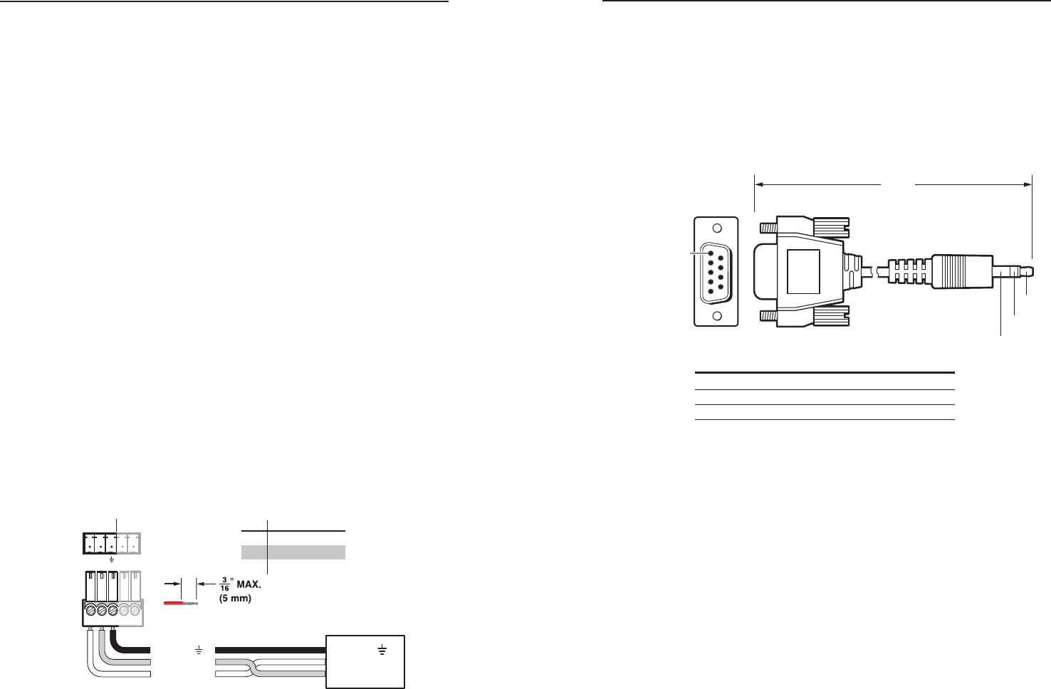
The optional 9-pin D to 2.5 mm mini jack TRS RS-232 cable,
part #70-335-01 (figure 3-2) can be used for connection to the
Configuration port.
6 feet
(1.8 m)
Part #70-335-01
5
1
9
6
Sleeve (Gnd)
Ring
Tip
9-pin D Connection TRS Plug
Pin 2 Computer's RX line Tip
Pin 3 Computer's TX line Ring
Pin 5 Computer's signal ground Sleeve
Figure 3-2 — Optional 9-pin TRS RS-232 cable
Simple Instruction Set Control
Host-to-interface communications
SIS commands consist of one or more characters per field. No
special characters are required to begin or end a command
character sequence. When a command is valid, the unit executes
the command and sends a response to the host device. All
responses from the unit to the host end with a carriage return
and a line feed (CR/LF =
]
), which signals the end of the
response character string. A string is one or more characters.
Symbol definitions
Symbols (variables), defined on the next page, are used
throughout the "Unit-initiated messages" section and the
command/response table beginning on page 3-8. The symbols
represent variables in the unit-initiated messages and the
command/response table fields.


