2
MPS602 • Setup Guide (Continued)
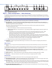
Analog Audio Input
k
Audio input group —Five 3.5mm, 5-pole captive screw connectors provide analog audio input to the switcher. Inputs
1-5 accept either balanced or unbalanced audio. Adjust the audio level of each analog audio input using the conguration
software or using the front panel (see Audio Input Level Adjustment on page4).
Unbalanced Stereo Input
Balanced Stereo Input
Tip
Ring
Tip
Ring
Sleeves
Do not tin the wires!
Tip
Sleeve
Sleeve
Tip
Unbalanced Mono Input
Balanced Mono Input
(high impedance)
Tip
Ring
Sleeve
LR
LR
LR
Tip
Sleeve
LR
Balanced Mic/Line Input
Tip
Sleeve
Ring
Tip
Sleeve
Unbalanced Mic/Line Input
Figure 2. Audio Input Connector Wiring
l
MicLine input — One 3-pole, 3.5mm captive screw connector connects a mic or mono line level audio device to the
MPS602 (see gure 2, right). Use the conguration software to select the mic or line input level.
m
Phantom Power and Mute HDMI — Two 2-position DIP switches.
MUTE HDMI AUDIO (on left) mutes the HDMI embedded audio on both the HDMI output (
e
) and the
DTP output (
i
) when the switch is UP .
PHANTOM POWER (on right) selects +48V phantom power for themic input in the UP position.
Program Audio Output
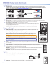
n
Variable audio output — 5-pole 3.5mm captive screw connector outputs the program audio. The
level is controlled by the front panel volume encoder.
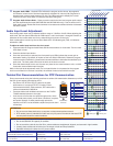
Connecting the 5-pole captive screw stereo output connector
Balanced or unbalanced program audio output is available on the MPS602 using a 3.5mm,
5-pole captive screw connector. Refer to the following illustration for proper wiring.
ATTENTION: For unbalanced audio output, connect sleeves to the center ground pin.
DO NOT connect sleeves to the negative (–) contacts.
NOTE: Do not tin the audio leads. Tinned wires are not as secure in the connector and
could be pulled out.
o
Mic Mix — One potentiometer controls the MicLine input level (
l
) mixed into the xed program
audio output(
p
).
p
Fixed audio output — The bottom 5-pole, 3.5mm captive screw connector is for balanced or unbalanced xed level
program audio output. The front panel knob does not control the audio level from this audio output port.
q
Amplified program audio output (SA and MA models only)
SA models — One green 4-pole, 5mm locking captive screw connector for amplied dual channel output to a
4 or 8 ohm speaker system.
MA models — One green 2-pole, 5mm locking captive screw connector for mono 70V output.
AMP OUT
CLASS 2 WIRING
70V
MPS 602M
L
R
AMP OUT
CLASS 2 WIRING
8Ω / 4Ω
L
R
SIG LINK
DTP IN
SIG LINK
DTP OUT
50/60 Hz
100-240V 1.0A MAX
1
2
RGB OUT
HDMI
MIC
MIX
RS-232
MPS 602 SA
Tx Rx G
MUTE HDMI AUDIO
PHANTOM POWER
SELECT
3
4
5
6
OUTPUTS
AMP OUT REMOTE
OVER DTP
OVER DTP
RS-232 IR
Rx GTx Tx Rx
RS-232 IR
Rx GTx Tx Rx
CLASS 2 WIRING
8Ω / 4Ω
INPUTS
AUDIO IN
AUDIO OUT
L 1 R L 2 R L 3 R
L VARIABLE R
L FIXED R
L 4 R L 5 R MIC LINE
R
L
R
SIG LINK
DTP IN
SIG LINK
DTP OUT
50/60 Hz
100-240V 1.0A MAX
1
2
RGB OUT
HDMI
MIC
MIX
MUTE HDMI AUDIO
PHANTOM POWER
SELECT
3
4
5
6
OUTPUTS
AMP OUT REMOTE
OVER DTP
OVER DTP
RS-232 IR
Rx GTx Tx Rx
RS-232 IR
Rx GTx Tx Rx
CLASS 2 WIRING
8Ω / 4Ω
INPUTS
AUDIO IN
AUDIO OUT
L 3 R
L VARIABLE R
L FIXED R
MIC LINE
Unbalanced Audio Output
Tip
No Ground Here
No Ground Here
Tip
Sleeves
LR
Balanced Audio Output
Tip
Ring
Tip
Ring
Sleeves
LR
Ground ( _ )
Receive (Rx)
Transmit (Tx)
Bidirectional
RS-232
Device
Ground ( _ )
Receive (Rx)
Transmit (Tx)
s
Reset button — Recessed button to return the MPS602 to factory default settings.
Control
r
RS-232 remote — 3-pole, 3.5mm captive screw connector for connection of a host computer,
or a controller using Simple Instruction Set (SIS™) or Windows-based control software. Wire the
connector as shown at right: