Installation, cont’d
TPS150 Switching and Transmission System • Installation2-4
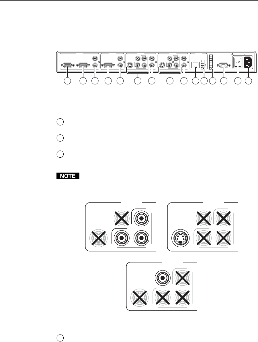
Cabling and Rear Panel Views
Transmitter connections
All connectors are on the rear panel (figure 2-3).
+
-
+
R
L
-
GND
PROJ PWR
VOL DN
VOL UP
IN4
IN3
IN2
IN1
LOCAL MONITOR
OUTPUT
AUDIO
L
R
RGB / VGA RGB / VGA
INPUT 2INPUT 1 INPUT 3
R-Y
B-YY
VIDEO
AUDIO
S-VIDEO
AUDIO
L
R
L
R
INPUT 4 OUTPUT
CONTACT
CLOSURE
AUDIO
R-Y
B-YY
VIDEO
AUDIO
S-VIDEO
L
R
UTP LINK
50–60 Hz
100–240 V .3A
3 3
1 12 4 4 5 84 4 1096 7
Figure 2-3 — TPT150 transmitter rear panel connectors
Video and audio input connections
1
Input 1 and Input 2 RGB/VGA video connectors — Connect RGBHV or
RGBS sources to these 15-pin HD female connectors.
2
Input 1 local monitor output connector — If desired, connect a local monitor
or other device to this 15-pin HD female connector.
3
Input 3 and Input 4 video connectors — Connect either component video,
S-video, or composite video sources to these BNC and 4-pin mini DIN
connectors.
For proper system operation, connect only one video format to input 3 and
input 4.
Connect the various video formats as shown in figure 2-4.
omponent
video
Composite
video
S-vide
R-Y
B-YY
VIDEO
S-VIDEO
R-Y
B-YY
VIDEO
S-VIDEO
INPUT 3
R-Y
B-YY
VIDEO
S-VIDEO
Figure 2-4 — Input 3 and input 4 video format connections
4
Input audio connectors — Connect unbalanced stereo or mono audio sources
to these pairs (left and right) of RCA connectors for audio input.


