5-2 AlphaServer DS20L User’s Guide
Figure 1-5 in the first chapter identifies the system LED indicators on the rear
of the system.
Table 5– 2 Rear System LED Status Indicators
LED Function
1
Steady red when system failure needs attention.
Off when the system is functioning properly.
2 Blinks amber to indicate system activity.
3
Blinks green when the system is in Standby mode.
Glows green to indicate that system power is on.
Glows red when the system power has failed.
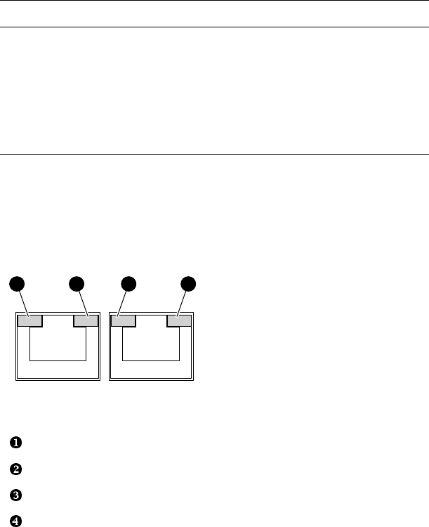
Figure 1-5 in the first chapter identifies the Ethernet network connectors on the
rear of the system. Figure 5-1 shows the LEDs in the upper corners of each
connector; Table 5–3 gives their meaning.
Figure 5-1 Network Connector LEDs
MR0288
1 2 43
Ethernet speed LED (for Tru64 UNIX on port 0; for Linux on port 1)
Ethernet activity LED (for Tru64 UNIX on port 0; for Linux on port 1)
Ethernet speed LED (for Tru64 UNIX on port 1; for Linux on port 0)
Ethernet activity LED (for Tru64 UNIX on port 1; for Linux on port 0)


