Hardware options installation 64
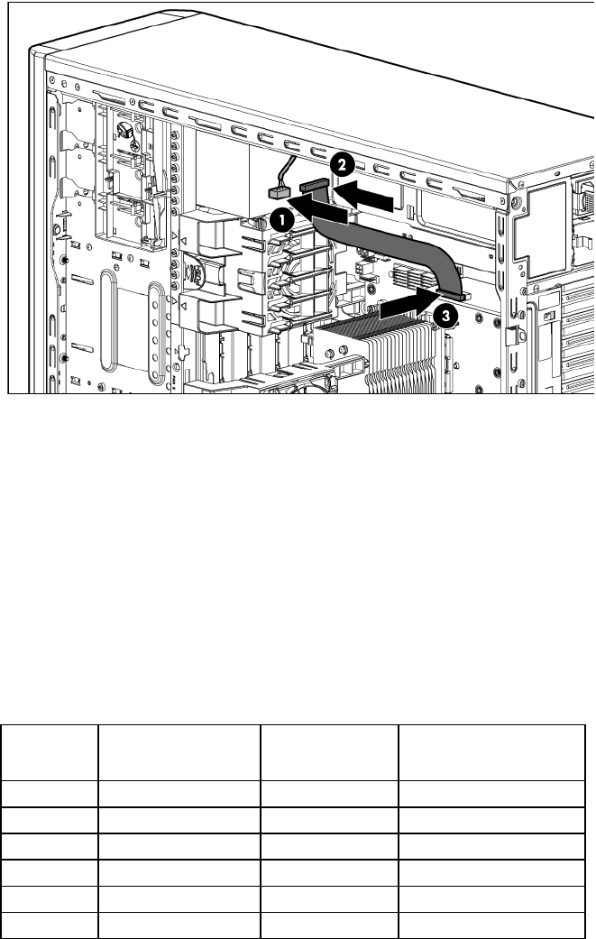
10. Connect the tape drive cable to the rear of the drive and to the SAS controller.
11. Remove the applicable bezel blanks from the bezel ("Remove a bezel blank" on page 24).
12. Install the access panel (on page 22).
13. Do one of the following:
o Close or install the tower bezel, as needed.
o Slide the server back into the rack.
14. Power up the server (on page 20).
Expansion board options
The server supports PCI Express and PCI-X expansion boards. Slot 1 is located on the optional PCI-X extender
board ("PCI-X extender board option" on page 66).
Slot Expansion
board type
Connector Maximum speed
1
PCI-X (optional) 64 bit, 3.3 V 100 MHz
2
PCI-X (optional) 64 bit, 3.3 V 100 MHz
3
PCIe1 x8 x1
4
PCIe2 x16 x16
5
PCIe2 x8 x4
6
PCIe2 x8 x4
Removing the expansion slot cover
1. Power down the server (on page 20).
2. Do one of the following:
o Open or remove the tower bezel, as needed ("Open or remove the tower bezel" on page 20).
o Extend the server from the rack (on page 21).
3. Remove the access panel (on page 21).


