Latch assembly
NOTE: All latch assembly kits include the latch, bracket, two screws, and spring.
Description Spare part number
Latch assembly 597837-001
Before removing the latch assembly, follow these steps:
1. Shut down the computer. If you are unsure whether the computer is off or in Hibernation, turn
the computer on, and then shut it down through the operating system.
2. Disconnect all external devices connected to the computer.
3. Disconnect the power from the computer by first unplugging the power cord from the AC outlet,
and then unplugging the AC adapter from the computer.
4. Remove the battery (see
Battery on page 39).
5. Remove the following components:
a. Hard drive cover (see
Hard drive on page 41)
b. Keyboard (see
Keyboard on page 48)
c. Top cover (see
Top cover on page 51)
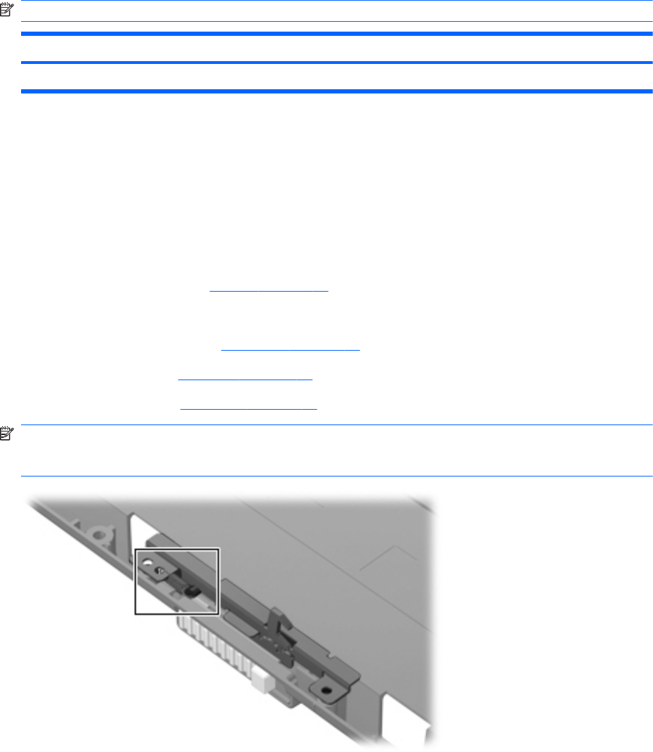
NOTE: The latch mechanism includes a small spring. Please note the installed location of this
spring in the following illustration prior to disassembling the latch mechanism to allow for correct
reassembly.
Remove the latch assembly:
1. Position the computer right-side up, with the front toward you.
2. Remove the two Phillips PM2.0×4.0 screws (1) that secure the latch bracket to the base
enclosure.
58 Chapter 4 Removal and replacement procedures ENWW


