Page 5 of 10 2993-xx2 - Rev: 3/11/2014 9:21 AM 9:21:55 AM
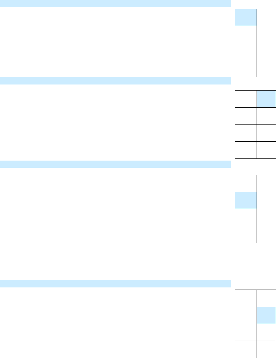
ON/OFF TOGGLE – Control Test
This button sends On and Off commands to unit under test.
1) Link Diagnostic Keypad as a controller of the unit under test.
2) Plug in Diagnostic Keypad at a test location.
3) Tap ON/OFF TOGGLE button.
Responder will turn on or off.
4) Move Diagnostic Keypad to other outlets if/as desired.
5) If unit testing is complete, UNLINK device.
BEEP – Signal Test
This button sends a beep command to unit under test. This allows you to test devices you don’t
wish to toggle on and off and/or from locations where you can hear the responder’s beep but
cannot see the unit under test.
1) Link Diagnostic Keypad as a controller of the unit under test.
2) Plug in Diagnostic Keypad at a test location.
3) Tap BEEP button.
Responder will beep (unless signal does not reach responder).
4) Move Diagnostic Keypad to other outlets if/as desired.
5) If unit testing is complete, UNLINK device.
REPORT Mode
This test allows you to monitor the quality of control signals from the device under test and is
commonly used to commission an installation. This mode does not require any links.
1) Plug in Diagnostic Keypad at a test location.
2) Tap REPORT button until its LED is illuminated.
3) Activate scenes from as many devices as you wish.
Keypad will beep at beginning of scene message.
Keypad will double-beep upon receipt of success report with no errors.*
Keypad will long-beep upon receipt of success report with errors.*
*The success report feature was released in devices shipped after March 2012.
A small number of INSTEON devices do not support this feature.
The delay between the beep and double-beep will vary depending on the number of responders in the scene.
o The delay for each responder is approximately 0.2 seconds (10 responders ~ 2 seconds).
o If the delay is longer, it may be an indication of difficulty in communications to one or more
responders.
TRAFFIC – Corruption and Noise Monitor
This test allows you to monitor in-band noise and INSTEON traffic on the powerline. This does not
require any links.
1) Plug in Diagnostic Keypad at a test location.
2) If button LED is not illuminated, tap the TRAFFIC button.
3) Observe TRAFFIC button LED for a few moments or minutes.
LED blinks indicate valid INSTEON messages.
Keypad will emit a long beep upon each corrupted message (commonly caused by
collisions/noise).
4) Initiate a scene from an INSTEON controller.
LED will blink during valid INSTEON traffic.
Excessive blinking is caused by message failures, commonly from a scene responder
ON/OFF
TOGGLE
BEEP
REPORT TRAFFIC
DISTANCE
LOCK/
UNLOCK
RELINK UNLINK
ON/OFF
TOGGLE
BEEP
REPORT TRAFFIC
DISTANCE
LOCK/
UNLOCK
RELINK UNLINK
ON/OFF
TOGGLE
BEEP
REPORT TRAFFIC
DISTANCE
LOCK/
UNLOCK
RELINK UNLINK
ON/OFF
TOGGLE
BEEP
REPORT TRAFFIC
DISTANCE
LOCK/
UNLOCK
RELINK UNLINK
