17-22 Vol. 3A
IA-32 ARCHITECTURE COMPATIBILITY
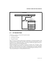
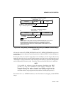
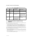
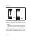
The content of CR4 is 0H following a hardware reset.
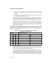
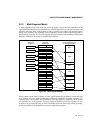
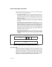
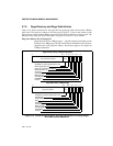
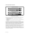
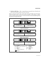
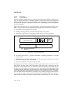
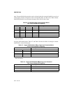
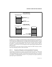
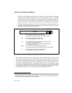
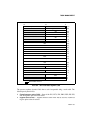
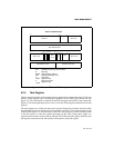
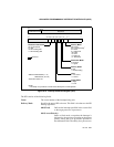
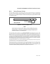
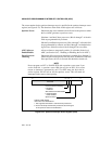
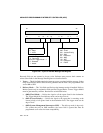
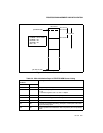
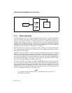
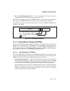
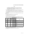
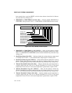
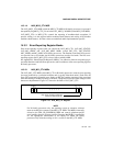
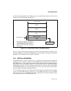
Control register CR4 was introduced in the Pentium processor. This register contains flags that
enable certain new extensions provided in the Pentium processor:
• VME — Virtual-8086 mode extensions. Enables support for a virtual interrupt flag in
virtual-8086 mode (see Section 15.3, “Interrupt and Exception Handling in Virtual-8086
Mode”).
• PVI — Protected-mode virtual interrupts. Enables support for a virtual interrupt flag in
protected mode (see Section 15.4, “Protected-Mode Virtual Interrupts”).
• TSD — Time-stamp disable. Restricts the execution of the RDTSC instruction to
procedures running at privileged level 0.
• DE — Debugging extensions. Causes an undefined opcode (#UD) exception to be
generated when debug registers DR4 and DR5 are references for improved performance
(see Section 18.2.2, “Debug Registers DR4 and DR5”).
• PSE — Page size extensions. Enables 4-MByte pages when set (see Section 3.6.1, “Paging
Options”).
• MCE — Machine-check enable. Enables the machine-check exception, allowing exception
handling for certain hardware error conditions (see Chapter 14, “Machine-
Check Architecture”).
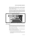
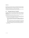
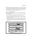
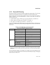
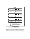
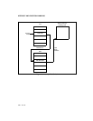
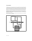
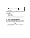
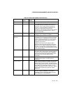
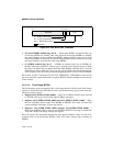
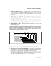
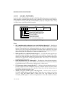
The Intel486 processor introduced five new flags in control register CR0:
• NE — Numeric error. Enables the normal mechanism for reporting floating-point numeric
errors.
• WP — Write protect. Write-protects user-level pages against supervisor-mode accesses.
• AM — Alignment mask. Controls whether alignment checking is performed. Operates in
conjunction with the AC (Alignment Check) flag.
• NW — Not write-through. Enables write-throughs and cache invalidation cycles when
clear and disables invalidation cycles and write-throughs that hit in the cache when set.
• CD — Cache disable. Enables the internal cache when clear and disables the cache when
set.
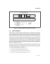
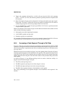
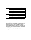
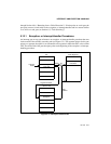
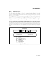
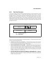
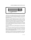
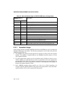
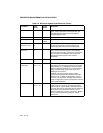
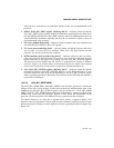
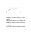
The Intel486 processor introduced two new flags in control register CR3:
• PCD — Page-level cache disable. The state of this flag is driven on the PCD# pin during
bus cycles that are not paged, such as interrupt acknowledge cycles, when paging is
enabled. The PCD# pin is used to control caching in an external cache on a cycle-by-cycle
basis.
• PWT — Page-level write-through. The state of this flag is driven on the PWT# pin during
bus cycles that are not paged, such as interrupt acknowledge cycles, when paging is
enabled. The PWT# pin is used to control write through in an external cache on a cycle-by-
cycle basis.