Toner Cartridge (TC) / TC Overall Composition Main Unit Theory of Operation
2-12
II Composition/Operation
3.3 Operation
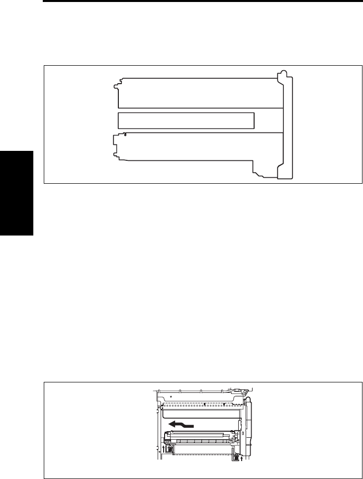
3.3.1 Configuration of Toner Cartridge
• The Toner Cartridge is U-shaped, positioned so as to enclose the Transfer Belt Unit. It
consists of three major sections: the Hopper, Developing Unit, and Connection.
3.3.2 Loading/unloading mechanism of Toner Cartridge
A. Loading procedure
• Hold the handle on the upper part of the Toner Cartridge with your left hand and support
the front face of the cartridge with your right hand.
• Position the Hopper in alignment with the rail on the machine side and insert the car-
tridge into the machine.
• When the upper handle contacts the machine frame, place it down and push the front
side of the cartridge with your right hand.
B. Pressure mechanism
• To avoid a contact between the Transfer Belt and Toner Cartridge, the Toner Cartridge is
inserted along the rail from a lowered position. The rail raises the cartridge as the car-
tridge reaches the rear end of the machine.
• At the same time that the cartridge is loaded in the machine, it is pressed into the prede-
termined position (upward) by springs in the order of its rear end and its front end.
• The pressure mechanisms provided at the front and rear ends ensure that the entire
pressure is not applied to the cartridge all at once.
• After the cartridge has been pressed upward, a lock pawl is engaged. The cartridge is
thus clicked in position to let the user know that it is properly loaded in position.
C. Drop preventive mechanism
• To prevent the Toner Cartridge from being dropped as it is unloaded, there is a drop pre-
ventive claw provided at the upper handle.
• Unless the upper handle is placed up, the cartridge is stopped halfway, which prevents
the cartridge from being slid out further.
4138to2005c2
Hopper
Developing Unit
ConnectionTransfer Belt Unit
4138to2009c1
5430DL_5440DL_5450_TO_PDF.book 12 ページ 2005年4月12日 火曜日 午後4時49分


