Locating parts on the system board
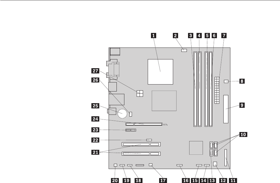
Figure 5 shows the location of parts on the system board.
1 Microprocessor 15 Front USB connector 1
2 Microprocessor fan connector 16 Front USB connector 2
3 Memory slot 1 17 Clear CMOS/Recovery jumper
4 Memory slot 2 18 Serial (COM2) connector
5 Memory slot 3 19 Front audio connector
6 Memory slot 4 20 Internal speaker connector
7 24-pin power connector 21 Adapter card slots (2)
8 Thermal sensor connector 22 Cover presence (Intrusion) switch connector
9 Diskette drive connector 23 PCI Express x1 adapter card slot
10 SATA connectors (3) 24 PCI Express x16 graphics adapter card slot
11 Parallel (LPT) connector 25 Battery
12 Power fan connector 26 System fan connector
13 eSATA connector 27 4-pin power connector
14 Front panel connector
Figure 5. System board parts locations
Chapter 8. Replacing FRUs - Tower computers 89


