cean Electric Winches 34 - 7
12345678
Black
Black
Grey
Not Used
SW 1
Electric Switch Kit
69000018
3
Grey
Not Used
SW 2
Electric Switch Kit
69000018
Blue
1
2
4
Thermal
Cutout
Isolator/Safety
Switch
Circuit
Breaker
Battery
EVC
Control Box
Battery +VE
Motor – VE
Battery –VE
Motor +VE
D1
D2
(Optional)
Vario Control
Two-way
Terminal Block
3 Amp
Fuse
BAT+
MOT+
BAT–
MOT–
A2
Fi
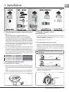
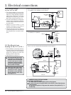
. 3.5.1
lso see
ection 3.7.
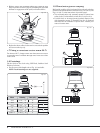
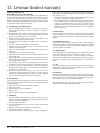
3.5 EV
E
ectr
c Var
a
e
Control.
tandard controller
ng
e spee
w
nc
es
34-48, 12 V
24 V
• T
e EVC winc
contro
er is a varia
e
spee
motor contro
er w
ic
can
rive
t
e winc
in 3
ifferent ways:
1. SW 1 drives the winch at full speed.
2. SW 2 drives the winch at a set speed
determined b
ad
ustable dial marked
(SP) on the control box. On suppl
the
dial is preset b
Lewmar to drive the
winc
at 60% of fu
s
ee
.
3. If optiona
Vario Contro
is fitte
t
en t
e winc
wi
rive at a spee
etermine
y a
justment of t
e Vario
Contro
w
en
ec
switc
SW 2
is
engage
• Th
EV
n
r
ll
r
rr
n
sensin
to halt the o
eration of the
win
h wh
n
h
win
h h
r
h
i
Maximum Safe Workin
Load.
• The EVC controller features a Ram
/
Soft Start to contro
t
e winc
start
up, a
justment of
ia
RA wi
vary t
e
start perio
etween 0.5 - 5 secon
s.
T
e
ia
is preset
y Lewmar for a start
eriod of 1 second.
• In order to ad
ust the speed (SP)
and Ram
(RA) dials, unscrew the
lu
screws, on to
of the controller
4 full turns and retract the
lu
/
screw assem
y. Use an e
ectrica
s
otte
2.5mm Max.
screw
river to
a
just t
e interna
ia
to t
e
esire
sett
ng
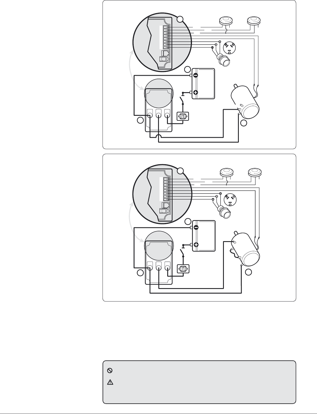
3
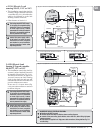
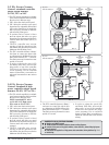
6 EV
E
ectr
c Var
a
e
Control. Standard & high
power controller sin
le speed
w
nc
es 50-65
12 V
24
• Th
EV
win
h
n
r
ll
r i
v
ri
l
s
eed motor controller which can drive
t
e winc
in 3
ifferent ways:
NOTE:
tandard EVC used
on 50−65 24 V. H
g
powe
EV
use
on 50−65 12 V
1. SW 1
rives t
e winc
at fu
spee
.
2. SW 2
rives t
e winc
at a set spee
determined b
ad
ustable dial marked
(SP) on the control box. On suppl
the
dial is preset b
Lewmar to drive the
winch at 60% of full s
eed.
3. If o
tional Vario Control is fitted
t
en t
e winc
wi
rive at a spee
etermine
y a
justment of t
e Vario
Contro
w
en
ec
switc
SW 2
is
engage
• Th
EV
n
r
ll
r
rr
n
sensin
to halt the o
eration of the
win
h wh
n
h
win
h h
r
h
i
Maximum Safe Workin
Load.
12345678
Black
Black
Grey
Not Used
SW 1
Electric Switch Kit
69000018
3
Grey
Not Used
SW 2
Electric Switch Kit
69000018
Blue
1
2
4
Isolator/Safety
Switch
Circuit
Breaker
Battery
EVC
Control Box
Battery +VE
Motor – VE
Battery –VE
Motor +VE
(Optional)
Vario Control
Two-way
Terminal Block
3 Amp
Fuse
BAT+
MOT+
BAT–
MOT–
Thermal
Cutout
F1
A2
A1
F2
Fi
. 3.6.1
lso see
ection 3.7.
• The EVC controller features a Ram
/
f
r
n
r
l
h
win
h
r
up, ad
ustment of dial RA will var
the
start
eriod between 0.5 - 5 seconds.
T
e
ia
is preset
y Lewmar for a start
perio
of 1 secon
.
• In order to ad
ust the speed (SP)
and Ram
(RA) dials, unscrew the
lu
screws, on to
of the controller
4 full turns and retract the
lu
/
screw assem
y. Use an e
ectrica
s
otte
2.5mm Max.
screw
river to
a
just t
e interna
ia
to t
e
esire
sett
ng
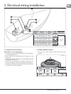
N
MBER KEY F
R ALL ELE
TRI
AL DIA
RAM
Ne
ative earth MUST be used
The deck switch wires MU
T be fi tted as shown on wiring diagrams
onnect all low power wiring
deck switches, motor cutout etc.
before fi tting high power
ca
es to contro
er
able boots are supplied for all high power cable connections, follow guidelines Fig. 2.1.1
or cable sizin