114
8170 N/B MAINTENANCE
5.1 Pentium 4(Willamette/Northwood) mFC-PGA2 478 pin
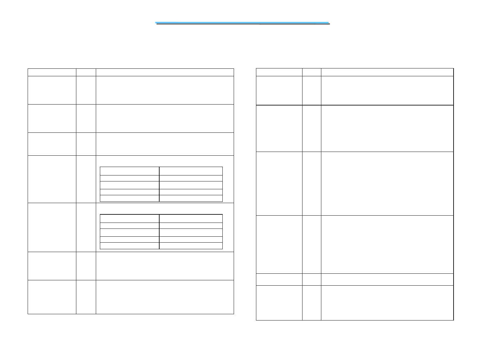
Name Type Description
DBSY#
Input/
Output
DBSY# (Data Bus Busy) is asserted by the agent responsible for
driving data on the processor system bus to indicate that the data
us is in use. The data bus isreleased after DBSY# is deasserted.
This signal must connect the appropriate pins on all processor
system bus agents.
DEFER#
Input
DEFER# is asserted by an agent to indicate that a transaction
cannot be guaranteed in-order completion. Assertion of
DEFER# is normally the responsibility of the addressed
memory or Input/Output agent. This signal must connect the
appropriate pins of all processor system bus agents.
DP[3:0]#
Input/
Output
DP[3:0]# (Data parity) provide parity protection for the
D[63:0]# signals. They are driven by the agent responsible for
driving D[63:0]#, and must connect the appropriate pins of all
Pentium 4 processor in the 478-pin package system bus gents.
DSTBN[3:0]#
Input/
Output
Data strobe used to latch in D[63:0]#.
Signals Associated Strobe
D[15:0]#, DBI0# DSTBN0#
D[31:16]#, DBI1# DSTBN1#
D[47:32]#, DBI2# DSTBN2#
D[63:48]#, DBI3# DSTBN3#
DSTBP[3:0]#
Input/
Output
Data strobe used to latch in D[63:0]#.
Signals Associated Strobe
D[15:0]#, DBI0# DSTBP0#
D[31:16]#, DBI1# DSTBP1#
D[47:32]#, DBI2# DSTBP2#
D[63:48]#, DBI3# DSTBP3#
FERR#
Output
FERR# (Floating-point Error) is asserted when the processor
detects an unmasked floating-point error. FERR# is similar to
the ERROR# signal on the Intel 387 coprocessor, and is
included for compatibility with systems using MSDOS*-type
floating-point error reporting.
GTLREF
Input GTLREF determines the signal reference level for AGTL+ input
pins. GTLREF should be set at 2/3 V
CC. GTLREF is used by the
AGTL+ receivers to determine if a signal is a logical 0 or
logical 1. Refer to the Intel® Pentium® 4 Processor in the
478-pin Package and Intel® 850 Chipset Platform Design
Guide for more information.
Name Type Description
HIT#
HITM#
Input/
Output
Input/
Output
HIT# (Snoop Hit) and HITM# (Hit Modified) convey
transaction snoop operation results. Any system bus agent may
assert both HIT# and HITM# together to indicate that it requires
a snoop stall, which can be continued by reasserting
HIT# and HITM# together.
IERR#
Output IERR# (Internal Error) is asserted by a processor as the result of
an internal error. Assertion of IERR# is usually accompanied by
a SHUTDOWN transaction on the processor system bus. This
transaction may optionally be converted to an external error
signal (e.g., NMI) by system core logic. The processor will keep
IERR# asserted until the assertion of RESET#, BINIT#, or
INIT#.
This signals does not have on-die termination.
IGNNE#
Input IGNNE# (Ignore Numeric Error) is asserted to force the
processor to ignore a numeric error and continue to execute
noncontrol floating-point instructions. If IGNNE# is deasserted,
the processor generates an exception on a noncontrol
floating-point instruction if a previous floating-point instruction
caused an error.IGNNE# has no effect when the NE bit in
control register 0 (CR0) is set. IGNNE# is an asynchronous
signal. However, to ensure recognition of this signal following
an Input/Output write instruction, it must be valid along with the
TRDY# assertion of the corresponding Input/Output Write bus
transaction.
INIT#
Input INIT# (Initialization), when asserted, resets integer registers
inside the processor without affecting its internal caches or
floating-point registers. The processor then begins execution at
the power-on Reset vector configured during power-on
configuration. The processor continues to handle snoop requests
during INIT# assertion. INIT# is an asynchronous signal and
must connect the appropriate pins of all processor system bus
agents. If INIT# is sampled active on the active to inactive
transition of RESET#, then the processor executes its Built-in
Self-Test (BIST).
ITPCLKOUT[1:0]
Output
The ITPCLKOUT[1:0] pins do not provide any output for the
Pentium® 4 processor in the 478-pin package. Refer to
ITP_CLK[1:0]
Input ITP_CLK[1:0] are copies of BCLK that are used only in
processor systems where no debug port is implemented on the
system board. ITP_CLK[1:0] are used as BCLK[1:0] references
for a debug port implemented on an interposer. If a debug port
is implemented in the system, ITP_CLK[1:0] are no connects in
the system. These are not processor signals.


