8
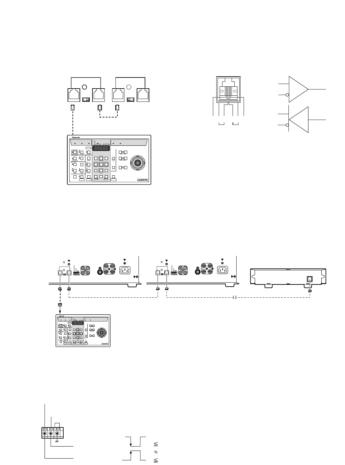
■ Connection between two or more color monitors and a device compat-
ible with Panasonic Security Data mode
In case of connecting multiple devices compatible with the Panasonic Security Data mode, connect the unit in a daisy-chain
configuration as shown below. The allowable connecting devices are up to 16 in a system. The maximum allowable cable
length of the system is approximately 500 m (1 650 ft).
■ Connection to the Standby On/Off Terminal
Connecting an external device to the STANDBY ON/OFF Terminal on the rear of the monitor enables control of the monitor dis-
play by input from that device, both in normal and standby display mode.
Shown below is an example of how to use this function.
■ Connection with the System Controller
If the optional 6-conductor cable assembly is used, simply plug one end of the cable into the DATA port of the Monitor and the
other end into the DATA port on the System Controller.
If you use cables assembled from locally procured materials, it is important that only high quality, data grade cable, suitable
for RS-485 communication (shielded 4-wire twisted pair cable), BELDEN 9406 or equivalent, is used.
Lower grade cable will result in unstable operation of the system.
PROGRAM
System Controller
WV
-
CU
360
ON OFF
TERMINATION
DATA
ON OFF
TERMINATION
DATA
To the
System Controller
G
N
D
G
N
D
TA TB RA RB
RA
RB
TA
TB
AUDIO
VIDEO
OUTIN OUT
A
IN
B
IN
A
IN
B
IN
OUT OUT
AC IN
S-VIDEO
G
STANDBY
ON
STANDBY
OFF
ON OFF
TERMINATION
FOCUS
DATA
DATA
AUDIO
VIDEO
OUTIN OUT
A
IN
B
IN
A
IN
B
IN
OUT OUT
AC IN
S-VIDEO
G
STANDBY
ON
STANDBY
OFF
ON OFF
TERMINATION
FOCUS
DATA
PROGRAM
System Controller
WV
-
CU
Termination: OFF Termination: OFF
Termination: ON
Termination: ON
Modular
cable
(Supplied:
WV-CU360)
To the Data port
(optional)
System Controller compatible
with PS•Data mode
Device compatible
with PS•Data mode
● Setting the Termination
Set the Termination Selector located on the rear of the
monitor according to your requirements.
ON: Data is terminated.
OFF: Data is sent to other equipment.
G
STANDBY
ON
STANDBY
OFF
VL 0.2 V
V
L 0.2 V
Hi-Z
V
H 5 V
Alarm Output
Alarm Reset Output
• STANDBY ON input
Pulse +5 V DC
• STANDBY OFF input
Non-voltage contact or open collector output
Note: To set up this function, refer to STANDBY ON in
the Display Setting menu.


