ASSEMBLY
Your new tractor has been assembled at the factory with exception of those parts left unassembled for shipping purposes.
To ensure safe and proper operation of your tractor all parts and hardware you assemble must be tightened securely. Use
the correct tools as necessary to insure proper tightness.
TOOLS REQUIRED FOR ASSEMBLY
A socket wrench set will make assembly easier. Standard
wrench sizes are listed.
(2) 1/2" wrenches Pliers
(1) 9/16" wrench Tire pressure gauge
Utility knife
When right or left hand is mentioned in this manual, itmeans
when you are in the operating position (seated behind the
steering wheel).
TO REMOVE TRACTOR FROM
CARTON
UNPACK CARTON
• Remove all accessible loose parts and parts cartons
from carton.
• Cut along dotted lines on all four panels of carton.
Remove end panels and lay side panels flat.
• Check for any additional loose parts or cartons and
remove.
BEFORE REMOVING TRACTOR FROM
SKID
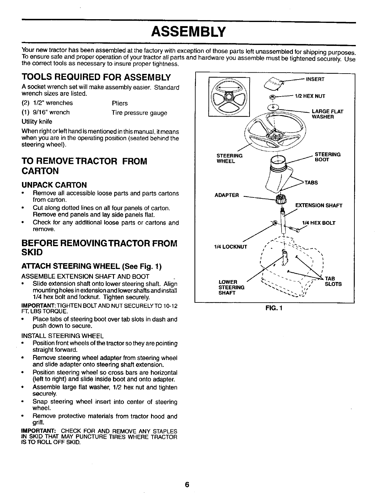
A'n'ACH STEERING WHEEL (See Fig. 1)
ASSEMBLE EXTENSION SHAFT AND BOOT
• Slide extension shaft onto lower steering shaft. Align
mounting holes inextension and Iowershafts and install
1/4 hex bolt and Iocknut. Tighten securely.
IMPORTANT:TIGHTEN BOLTAND NUT SECURELYTO 10-12
FT.LBS TORQUE.
• Place tabs of steering boot over tab slots in dash and
push down to secure.
INSTALL STEERING WHEEL
• Position front wheels of the tractor so they are pointing
straight forward.
• Remove steering wheel adapter from steering wheel
and slide adapter onto steering shaft extension.
• Position steering wheel so cross bars are horizontal
(left to right) and slide inside boot and onto adapter.
• Assemble large flat washer, 1/2 hex nut and tighten
securely.
Snap steering wheel insert into center of steering
wheel.
• Remove protective materials from tractor hood and
grill.
IMPORTANT: CHECK FOR AND REMOVE ANY STAPLES
IN SKID THAT MAY PUNCTURE TIRES WHERE TRACTOR
IS TO ROLL OFF SKID.
STEERING _/
WHEEL
ADAPTER ---___.__.._..._
WASHER
STEERING
BOOT
_i_ TABS
EXTENSION SHAFT
1/4 HEX BOLT
114LOCKNUT " . " _
LOWER
STEERING
SHAFT
FIG. 1
6


