Hawk 2 (Wide bus) Family Install Guide, Rev. C
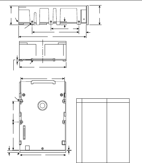
Figure 5. Hawk 2 family ST12400WC model drive
mounting configuration dimension (80 pin
I/O connector)
A
F
D
E
C
[1]
[3]
B
G
J
H
K
[2]
Notes:
[1]
[2]
[3]
[4]
[5]
Inches Millimeters
5.74
4.00
1.620
2.362
.620
4.000
.250
1.750
3.750
2.370
1.725
4.100
0.19
0.015
0.181
145.80
101.60
41.15
60.00
15.75
101.60
6.35
44.45
95.25
60.20
43.82
104.14
4.83
0.381
4.597
A
B
C
D
E
F
G
H
J
K
L
M
N
P
R
0.010
0.010
0.026
0.021
0.010
0.010
0.010
0.018
0.010
0.010
0.010
0.010
0.010
0.010
0.018
0.013
±
±
+
–
±
±
±
±
±
±
±
±
±
±
max
+
–
.25
.25
.66
.53
.25
.25
.25
.46
.25
.25
.25
.25
.25
.25
.45
.33
L
[4]
M
N
[4]
P
Mounting holes three on each side, 6-32 UNC.
Max screw length into side of drive 0.15 in.
(3.81 mm). Screw tightening torque 8.0 in-lb
(.90 NM) max with minimum thread engage-
ment of .12 in. (3.00 mm).
Mounting holes four on bottom, 6-32 UNC.
Max screw length into bottom of drive 0.20 in.
(5.08 mm). Screw tightening torque 8.0 in-lb
(.90 NM) max with minimum thread engage-
ment of .12 in. (3.00 mm).
Power and interface connections can extend past
the "A" dimension by 0.040 in. (1.02 mm).
Decorative front panel.
Connector is centered (side to side) on drive
within ±0.020 in. (.508 mm).
±
±
+
–
±
±
±
±
±
±
±
±
±
±
max
+
–
R
Connector Centerline
[5]
Pin 1
35


