SONANCE • 212 Avenida Fabricante • San Clemente, CA 92672
Pg 3
adjacent cabinet wall or door a short distance from the unit's sensor. Another instance is
when you place an emitter inside the device, but cannot place it close to the IR sensor. In
such cases, you may need the extra power of the high power mode to blast through
printed circuit boards or around chassis structures. In addition, when using the lower
output VE1 and VE2 Blink IR's, you may need the high power mode for some devices that
have less sensitive IR sensors.
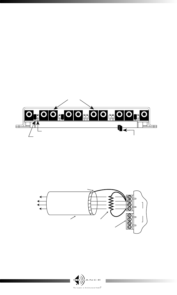
3. The resistors also provide current sharing to each emitter and allow the use of dual emit-
ters in combination with single emitters.You may, therefore, connect any combination of
emitter models E1, VE1, E2 & VE2 in the same system, as illustrated in Fig. 2, to drive the
desired number of devices.
When using less than 10 of the emitter ports, you may plug into any of them without regard
to order.
IMPORTANT NOTE: When using lengths greater than250 ft.) of inter-room shielded cable, it may be
necessary to connect a 470 Ohm 1/8 watt resistor between input terminals of Sonance connecting
blocks (CB1, CB2Z, ACB1), zone controllers, etc.
MOUNTING: The ACB1 can be conveniently mounted to a wall or shelf by using screws or
mounted into a 3” SNAPTRACK. (SNAPTRACK is a registered trademark of AUGAT)
needed. See note 2.