E6581301
B-13
2
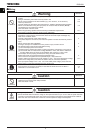
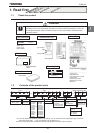
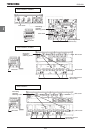
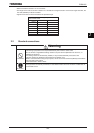
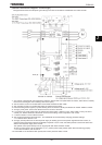
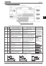
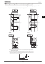
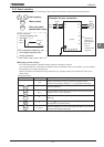
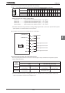
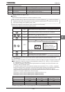
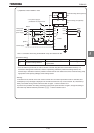
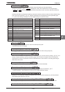
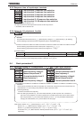
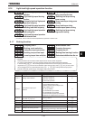
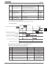
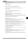
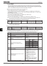
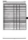
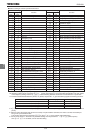
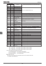
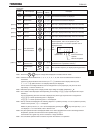
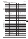
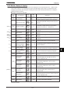
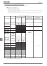
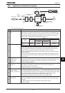
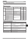
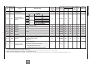
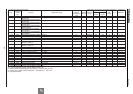
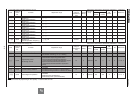
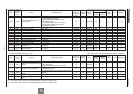
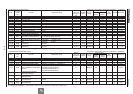
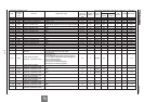
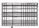
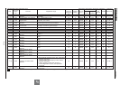
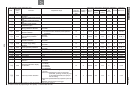
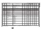
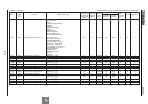
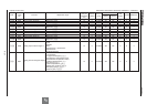
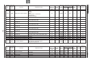
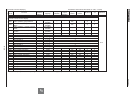
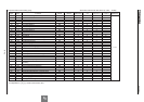
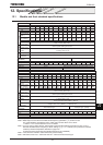
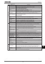
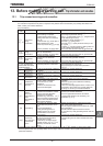
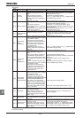
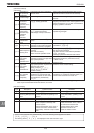
Terminal
symbol
Input/
output
Function (Sink Source logic)
Electrical
specifications
Inverter internal circuits
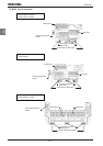
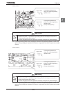
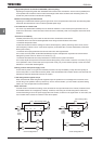
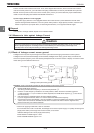
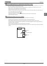
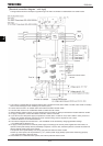
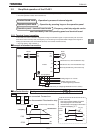
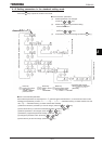
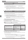
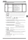
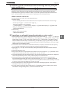
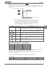
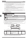
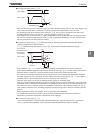
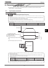
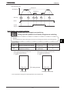
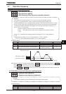
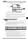
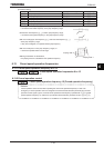
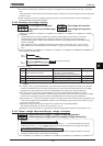
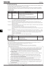
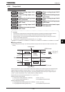
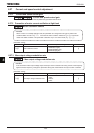
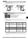
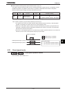
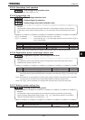
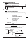
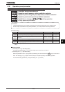
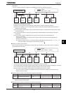
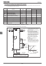
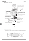
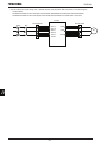
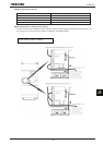
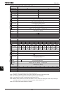
+SU
Input
DC power input terminal for operating the
control circuit. Connect a control power backup
device (optional) between +SU and CC.
Voltage:24Vdc±10%
Use a power supply
with a current rating
of 1.05A or more.
(In case of not install
options, current rating
is 300mA )
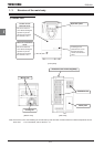
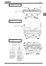
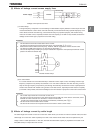
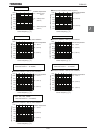
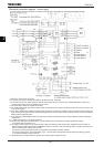
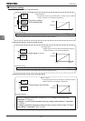
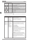
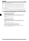
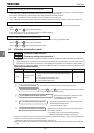
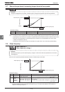
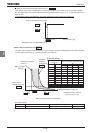
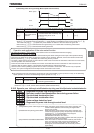
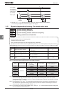
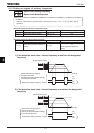
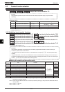
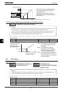
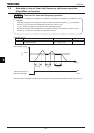
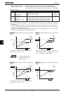
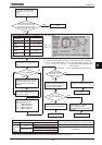
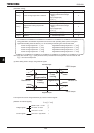
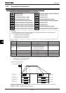
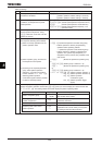
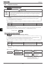
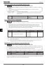
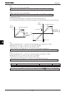
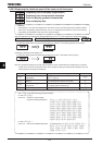
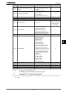
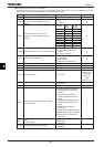
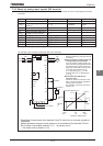
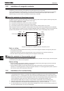
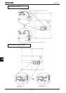
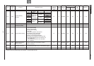
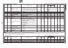
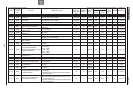
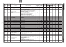
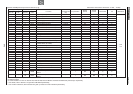
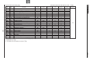
FLA
FLB
FLC
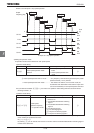
Output
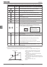
Relay contact output. Contact rating
Used to detect the activation of the inverter's
protective function. Contact across FLA-FLC is
closed and FLB-FLC is opened during
protection function operation.
250Vac-2A
30Vdc-1A
:at resistance load
250Vac-1A
:cosφ=0.4
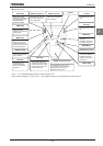
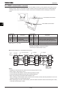
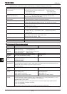
l
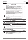
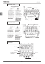
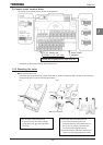
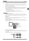
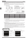
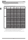
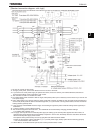
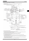
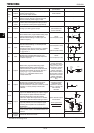
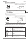
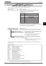
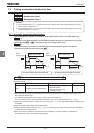
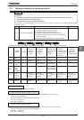
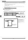
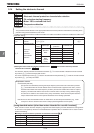
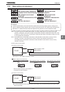
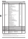
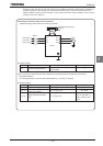
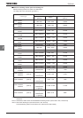
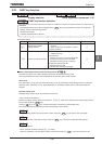
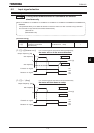
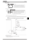
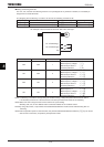
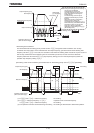
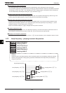
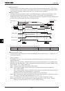
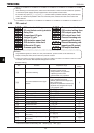
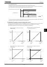
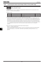
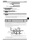
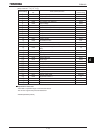
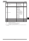
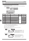
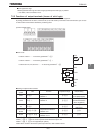
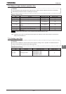
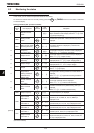
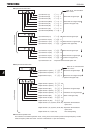
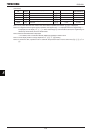
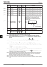
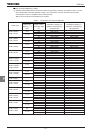
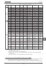
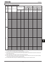
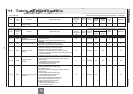
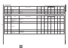
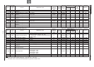
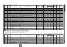
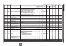
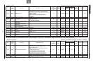
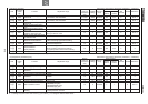
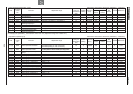
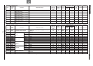
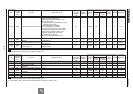
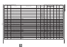
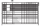
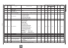
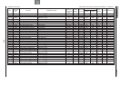
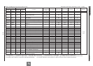
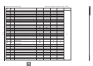
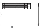
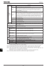
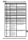
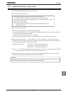
SW SW settings
Default setting
(Settings marked
with Ɣ)
Function
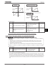
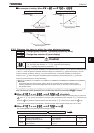
SW1
Ɣ
(-H1,HN,WN)
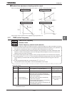
Setting for using the inverter’s internal power supply in sink logic
mode
Setting for using the inverter’s external power supply in sink logic
mode
Ɣ
(-WP)
Setting for operating the inverter in source logic mode
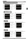
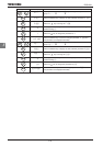
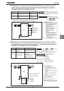
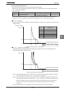
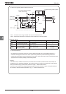
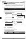
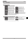
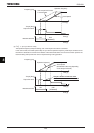
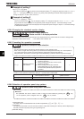
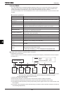
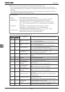
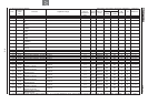
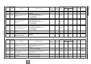
SW2
Ɣ
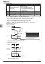
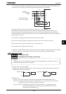
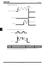
Setting for using the analog output terminal FM to output current
of 0-1mA
Setting for using the analog output terminal FM to output current
of 0-10V or 0-20mA (4-20mA)
0-10V (H=) or 0-20mA (H=) can be selected by
changing parameter settings.
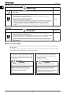
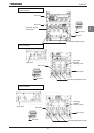
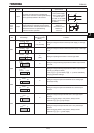
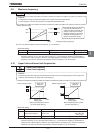
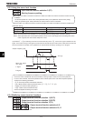
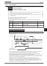
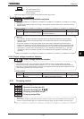
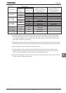
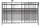
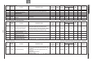
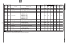
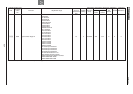
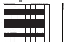
SW3
Ɣ
Setting for using the input terminal RR/S4 as an analog input
terminal (0-10Vdc)
Setting for using the input terminal RR/S4 as a contact input
terminal
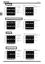
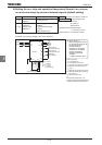
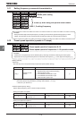
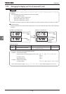
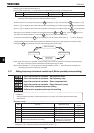
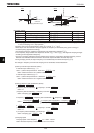
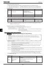
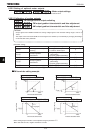
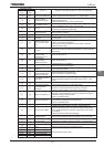
SW4
Ɣ
Setting for using the output terminal OUT1 as a logic output
terminal
When turning the switch to this position, always set the
parameter H to (logic output).
Setting for using the output terminal OUT1 as a pulse output
terminal
When turning the switch to this position, always set the
parameter H to (pulse output).
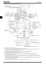
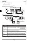
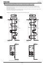
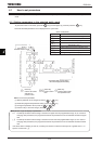
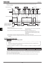
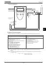
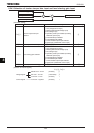
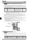
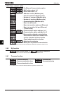
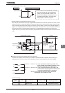
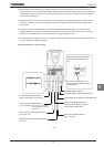
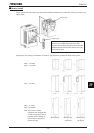
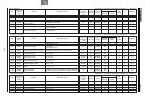
0-20mA
0-20mA
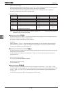
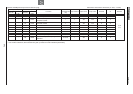
P24
FL
FLA
FLB
FLC
P24
1
+SU
CC