10
Installation
(continued)
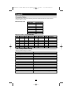
Multilevel Installations
The number of computers that can be added to your installation can be greatly expanded by performing a
multilevel installation. The B060-032 supports three types of multilevel installation:
• Daisy chained
• Cascaded
• Daisy chained plus cascaded
Overview
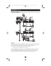
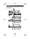
Daisy chaining refers to connecting two KVM switches via dedicated daisy chain ports. The switches are
strung together in a chain (see the diagram on p. 11).
With daisy chaining, none of the switch’s CPU ports are used to connect to the next switch. The port
capacity of a daisy-chained installation is the total of all the CPU ports of all the KVM switches on the
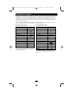
chain. For example, a B060-032 has 32 CPU ports. On an installation with eight daisy-chained switches
the number of available ports is 32 x 8 = 256.
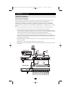
Cascading involves using the CPU ports of a Parent KVM switch (one that is above a switch linked down
from it) to connect to a Child KVM switch. Cascading adds capacity to a KVM installation, but the parent
loses one CPU port for each cascaded KVM.
The B060-032 supports both daisy chaining and cascading. In addition, it supports combining the two
methods—providing enormous capacity and flexibility for expanding the installation. The following sec-
tions provide the information and procedures involved in setting up the various multilevel installations.
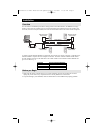
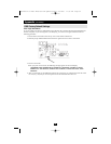
Daisy Chaining
Up to 7 additional B060-032 units can be daisy chained together; each capable of supporting four inde-
pendent consoles. The first B060-032 is considered the Master unit; the daisy chained B060-032s are con-
sidered Slaves.
In a complete daisy chained installation, the four consoles that belong to the Master switch can access and
control all of the computers (up to 256) on the installation. The four consoles belonging to each Slave
switch only control the computers (up to 32) connected to their switch.
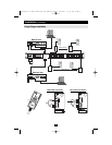
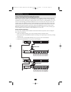
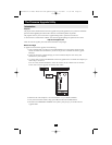
To set up a daisy chained installation, refer to the diagram on page 11 and do the following:
1. Make sure that power to all the devices you will be connecting up has been turned off.
2. Use a daisy chain cable set (described in the Cables section, p. 3), to connect the Chain Out port of
the parent B060-032 unit to the Chain In port of the child B060-032 unit (First Station Out to
Second Station In, Second Station Out to Third Station In, etc.).
Note: You cannot use the Chain In port of the First Station B060-032, since it is the highest level
parent.
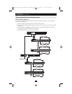
3. If you wish to install any consoles on this switch, follow the procedure described for the Single
Stage Installation on p. 8.
4. Use Cat5e cabling and a Server Interface Module (described in the Cables section, p. 4), to connect
any available CPU Port on the B060-032 to the Keyboard, Video and Mouse ports of the comput-
ers you are installing.
5. Repeat the above steps for any additional B060-032 units you wish to add to the chain.
6. Plug the power cord into an AC power source and into the B060-032's power socket.
7. Power up the installation according to the following procedure:
a. Switch on the power for the First Station. Wait for the unit to ascertain its Station ID and dis-
play it on the Station ID LED. (The Station ID for the First Stage unit is 01, the ID for the
Second Stage unit is 02, the ID for the Third Stage unit is 03, etc.).
b. Switch on the power for each Station on the installation in turn (Second Station, then Third
Station, etc.). In each case, wait for the Station ID to be ascertained and displayed on the cur-
rent Station before powering on the next one.
c. After all the Stations are up, power on the computers.