6
1
2
N(L2)
GROUND
L(L1)
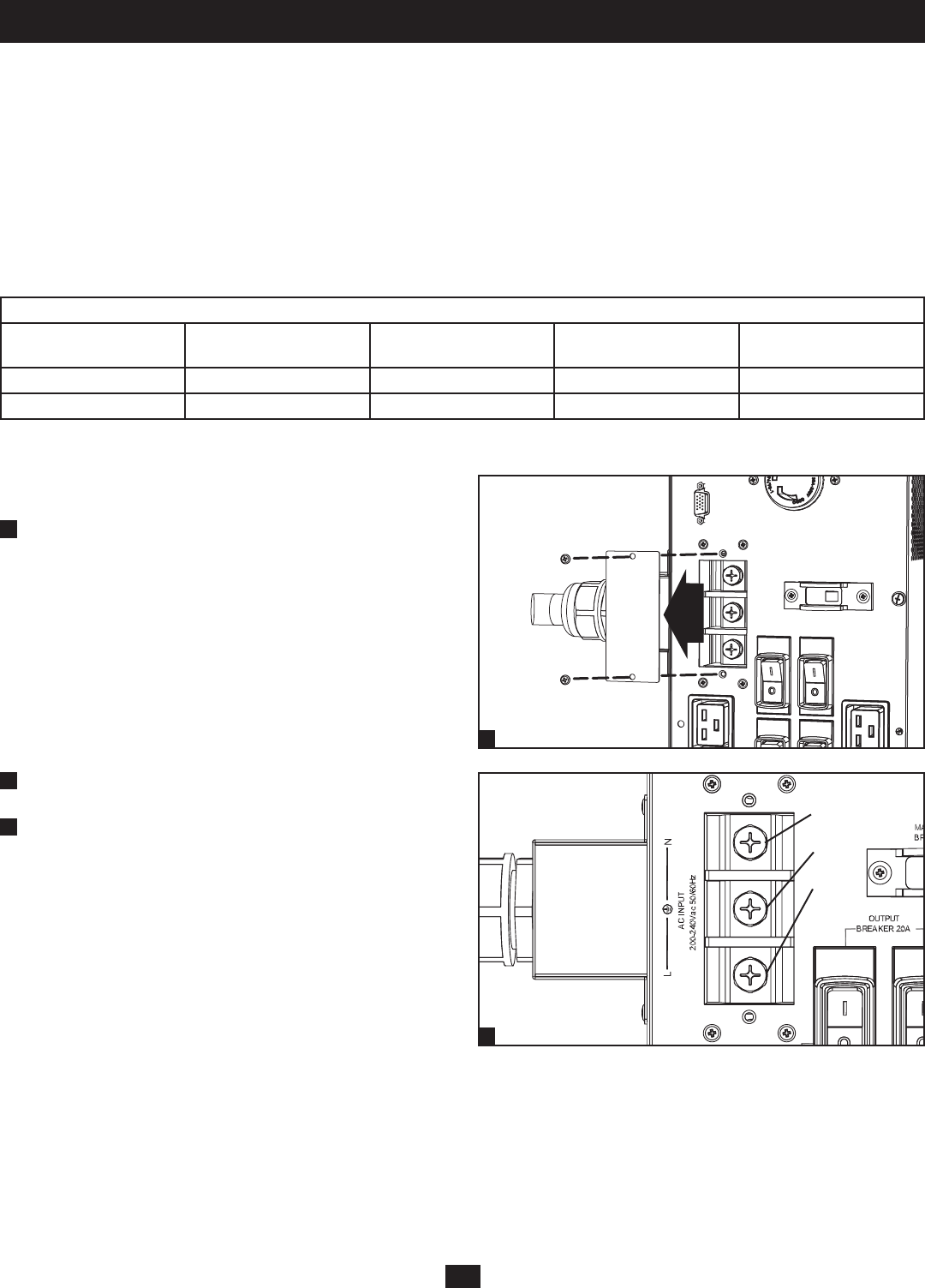
Connection
Terminal Wiring Connections
SUPDMB20K & SUPDMB20KIEC
1
Unscrew the 2 screws to remove the Input Terminal Access covers.
2
Connect the N (L2), Ground and L (L1) input wires according to
markings on the connectors as seen in the diagram.
3
After input wire attachments have been made, replace the Input
Terminal Access covers.
Hardwiring Cautions
• Wiring must be done by a qualied electrician.
• When making wiring connections, observe the cable connection regulations appropriate to your area [e.g. National Electrical Code (NEC) in the
U.S.] at all times. Be sure to install an easily accessible disconnect switch in your installation wiring so you may cut off the UPS’s AC input during
res and other emergencies. Ensure that cables are tted with cable sleeves and are secured by connector clamps. Tighten connections with a
torque of not less than 24-28 inch-pounds (2.7-3.2 NM).
• Make sure that your equipment is properly grounded.
• Using cables of improper size may damage your equipment and cause re hazards. Choose appropriate cabling and protection circuits to make
wiring connections. Ground conductors must be the same size and type as the power conductors used.
• Refer to National Electrical Code (NEC) guidelines for proper wire gauge and output protection circuit requirements.
Input and Output Ratings*
Model Input Voltage
Maximum Rated Input
Current
Maximum Rated Output
Current
Typical Wire Size
8kVA 200-240V (L-N) 46 A 40 A 8 mm
2
=8 AWG
10kVA 200-240V (L-N) 56 A 50 A 8 mm
2
=8 AWG
*Ratings shown are for redundancy parallel mode; when paralleling for power, the ratings will be doubled.


