6
SM-165
OPERATION 3
• Un-coil electrical cord from inside the front cover and plug it in a properly
grounded outlet. Press the reset button on the GFCI plug.
• Un-coil Feeder Gun Assembly and connect it to the unit using the shaft con-
nector and electrical connector.
• At this point the green light will come on to show that you have power inside
the unit.
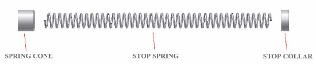
• Install the Shaft & Casing Length Stop Unit on to the Shaft & Casing:
1. Remove Shaft Stop Nut from the New Shaft & Casing (might be already
removed)
2. Insert the Stop Collar
3. Insert the Stop Spring
4. Insert the Spring Cone
The Spring and the Spring Cone must be on the brush side of the Stop Collar.
• At this point place the unit on its wheels and bumper so that there is an easy
access to the shaft & casing inlet on the bottom of the unit. Now remove the
bottom protection cover with 5 thumb screws. (must also remove handle pins
to remove the bottom cover) Then feed the Shaft in to the Shaft & Casing Inlet,
thru the stop switch plate and housing and guide the tip to the feed wheel.
- If using 1/2” Dia. Shaft guide it into the large groove.
- If using 3/8” Dia. Shaft guide it into the small groove.
• Attach the Shaft & Casing to the Shaft Drive Connector. Once the tip is
grabbed between the feed wheel and the edge, Press the “Forward Trigger” in
pulses until the tip of the Shaft & Casing comes out from the tip of the Gun.
*At this point, to make the initial feeding easier make sure the shaft is spinning
and that the flex hose on the feeder gun is straight. It is easier to go in pulses and
guide the tip of the shaft & casing thru the flex hose. If there is any resistance going
forward then reverse with a pulse or two and then go forward again.
7
SM-165
OPERATION 4
• Screw back on the bottom protection cover, re-install the handle pins and lay
down the unit in operation position.
• Connect water hose to water inlet, with the strainer within. Turn water supply
on. *Solenoid valve only opens to allow water through when the motor is run-
ning.
• Attach the appropriate brush on to the shaft tip.
• Send the brush inside the tube to be cleaned and make the final adjustment for
the Shaft & Casing Length Stop Unit on the Shaft & Casing. To adjust the stop
unit, loosen the hex screws on the stop collar and slide it to the desired posi-
tion. Retighten screws.
• After the length of the tube to be cleaned is decided with the stop collar. Just
send in the brush by pressing the top of the trigger. Once the Stop Collar on the
shaft and casing hits the stop switch plate the unit will stop sending the shaft &
casing forward. So at this time Press the bottom of the trigger and bring back
the brush out of the tube. When exiting the tube, hold the gun a few inches
from the tube head and when you see the brush passing by, release the trigger.
• Repeat the cycle by just holding the forward trigger until the shaft & casing
doesn't move forward anymore and then reversing the brush until it comes out
of the tube.
LARGE GROOVE
SMALL GROOVE
FEED WHEEL
STOP SWITCH
PLATE


