18 Owner Service
29977 (Rev. 1/23/2009)
BLADE SERVICING
NOTICE
■ Do not handle blades with bare hands. Care-
less or improper handling may result in serious
injury.
Raise wings and lock in up position. Inspect blades
before each use to determine that they are properly
installed and in good condition. Check to be sure
blades are snug but still swivel on blade pin (see Blade
Installation). Replace any blade that is bent, exces-
sively nicked, worn or has any other damage. Small
nicks can be ground out when sharpening.
Blade Removal
Align crossbar and blade pin assembly with blade
access hole in cutter frame. Remove bolt (1) and blade
pin lock clip (2). Slide keyhole plate (3) out of blade pin
groove and remove. Remove spacers and drive pin out
of crossbar.
NOTICE
■ If blade is seized in crossbar and extreme force
will be required to remove it, support crossbar
from below to prevent gearbox damage.
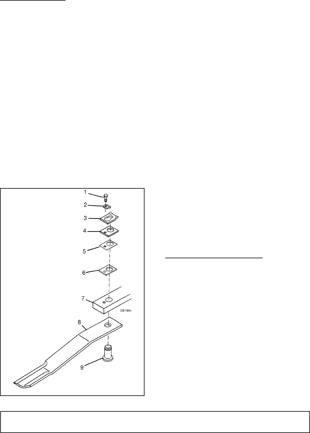
Figure 4. Blade Removal
Blade Installation
Apply liberal coating of Never Seez
®
or equivalent to
blade pin and crossbar hole. Make sure blade is offset
away from deck with cutting edge toward direction of
rotation. Install pin (9) through blade (8) and push up
tightly against crossbar (7). Install as many spacers as
possible, allowing enough space for keyhole plate (3)
to slide into groove of blade pin. Keyhole plate (3) must
be installed with formed ears up as shown. Insert lock
clip (2) over keyhole plate and into blade pin groove
and secure with bolt (1). When installation is complete,
blade should be snug, but still swivel on pin without
excessive force. Retain any spacers not used in shim-
ming blade to be used when either installing new blade
or when blade wear occurs.
NOTICE
■ Crossbar rotation is counter-clockwise when
looking down on the cutter.
■ When sharpening blades grind each blade the
same amount to maintain balance. When replacing
blades, replace in pairs. Unbalanced blades will
cause excessive vibration which can damage gear-
box bearings. Vibration may also cause structural
cracks in cutter housing.
Blade Sharpening
Always sharpen all blades at the same time to maintain
balance. Follow original sharpening pattern. Do not
sharpen blade to a razor edge, but leave at least a
1-1/16" blunt edge. Do not sharpen back side of blade.
SLIP CLUTCH ADJUSTMENT
A slip clutch is designed to slip, protecting the gearbox
and driveline, should the cutter strike an obstruction.
When a unit sets for a long period of time, such as win-
ter storage, the clutch can rust and seize. When this
occurs, loosen the spring tension and pry clutch plates
apart. Engage PTO and slip clutch. Adjust clutch as
specified.
The maximum the springs should be compressed on a
standard clutch is 1-3/4" at dimension “A”.
For a heavy-duty clutch and wing drive clutches, com-
press springs a minimum of 1-25/32" and a maximum
of 1-13/16" at dimension “A”.
If a clutch continues to slip with springs compressed to
the maximum settings, check friction discs for exces-
sive wear. Discs are 1/8" thick when new. Replace after
1/32" wear. (Minimum disc thickness is 3/32".)
1. 1/2 NC x 1-1/4 HHCS GR5
2. Blade lock clip
3. Keyhole plate
4. 3/16” Spacer
5. Shim, 20 ga
6. Shim, 18 ga
7. Crossbar assembly
8. Blade
9. Blade pin


