Chapter 2 Hardware Description and Connection
GS1100 Series User’s Guide
17
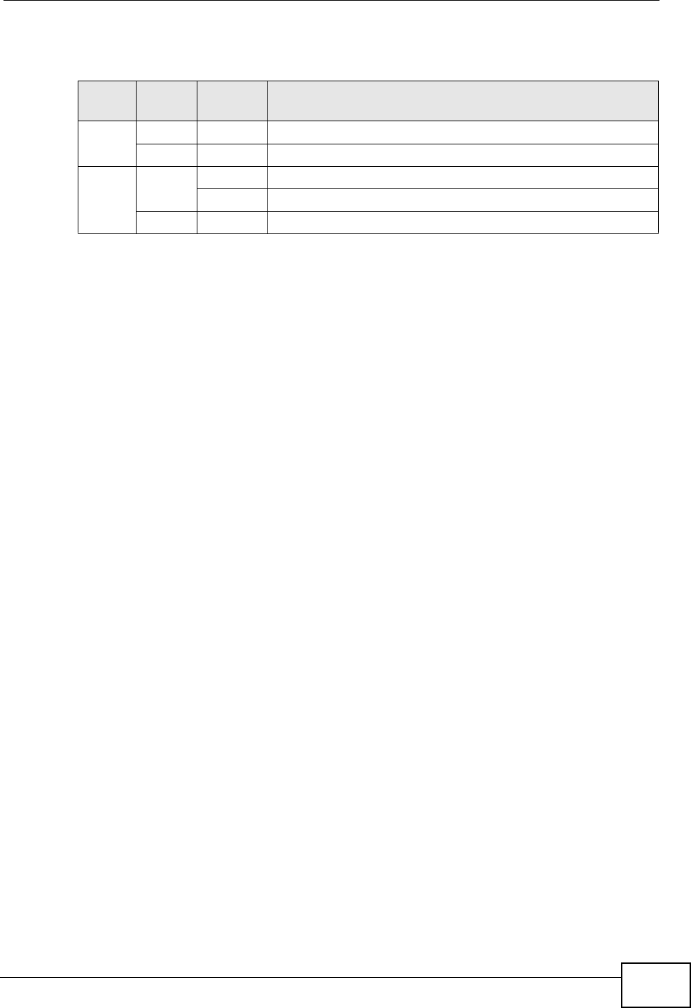
The following table describes the LEDs.
2.3 Hardware Installation
For GS1100-16, you can place the Switch directly on top of your desk or have it
rack-mounted. For GS110-24, the size is suitable for rack-mounting and you can
refer to Section 2.3.2 on page 18 for instruction. Take note of the following:
• The Switch should have a minimum 25 mm space around it for ventilation.
• The Switch should be placed in a desk that has a level surface and that is able to
support the weight of the Switch.
To start using it, simply connect the power cables and turn on the Switch.
Note: The GS1100-16 is a desktop device, but it is also rackmountable and wall-
mountable. Ask an authorized technician to attach the Switch to the rack/
wall.
2.3.1 Wall Mounting (GS1100-16 Only)
Do the following to attach your Switch to a wall.
1 Screw the two screws provided with your Switch into the wall 150 mm apart (see
the figure in step 2). Use screws with 6 mm ~ 8 mm (0.24" ~ 0.31") wide heads.
Do not screw the screws all the way in to the wall; leave a small gap between the
head of the screw and the wall.
The gap must be big enough for the screw heads to slide into the screw slots and
the connection cables to run down the back of the Switch.
Note: Make sure the screws are securely fixed to the wall and strong enough to hold
the weight of the Switch with the connection cables.
Table 2 The Front Panel LED Descriptions
LED
COLO
R
STATUS DESCRIPTION
PWR Green On The Switch is on and receiving power.
Off The
Switch is not receiving power.
LINK/
ACT
Green On The port is connected to an Ethernet network.
Blinking The port is receiving or transmitting data.
Off The port is not connected to an Ethernet network.


