PoE-80 User’s Guide
12
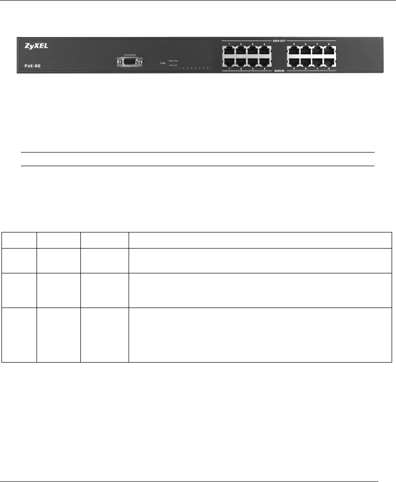
2.4 Front Panel Connections
The DATA OUT ports send power and data to the PoE-enabled devices. Use Ethernet cables to
connect the eight DATA OUT RJ-45 Ethernet ports to PoE-enabled devices.
Use Ethernet cables to connect the eight DATA IN RJ-45 Ethernet ports to the LAN.
The maximum Ethernet cable length is 100m.
Use a console cable to connect the console port to a management computer.
2.5 Front Panel LEDs
The LEDs give real-time information about the system’s operational status.
LED COLOR STATUS MEANING
PWR Green On
Off
Power is being supplied to the PoE-80.
No power is being supplied to the PoE-80.
PWR
FWD
Green
On
Off
The DATA OUT port is connected and sending power to an
Ethernet device.
The DATA OUT port is not sending power to an Ethernet device.
PWR
OFF
Orange
On
Off
The Ethernet device connected to the PoE-80’s DATA OUT port
requires more power than the PoE-80 can provide or the
Ethernet cable is shorted.
The connection to the Ethernet device is functioning properly or
no Ethernet device is connected to the DATA OUT port.
3 Software Utility Installation
Install the software utility in order to configure the PoE-80 PD. You can easily view the PoE-80’s
power parameters and control it through the software utility. The software utility provides an easy-
to-use GUI interface. The software utility is compatible with Windows 2000 and XP. Please follow
the below steps to install the software utility. You may need to use your Windows CD during the
installation.


