4
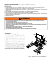
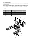
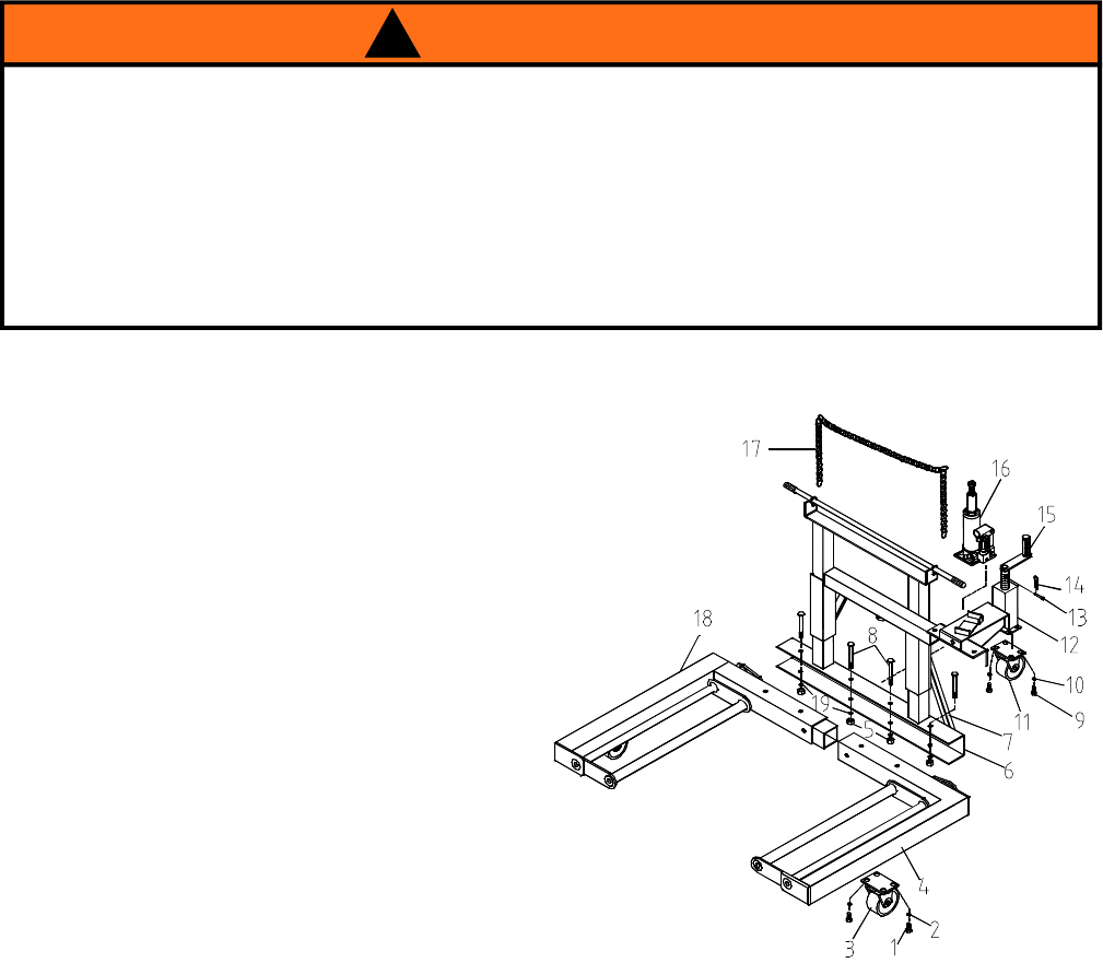
ASSEMBLY (refer to Figure 3)
1. Attach front casters (No. 3) into right main frame (No.
4) and left main frame (No. 18) with M12x25 bolts and
washers (No. 1 & 2).
2. Attach rear caster (No. 11) into rear support assem-
bly (No. 12), with M18x20 bolts and washers (No. 9
&10).
3. Insert left main frame (No. 18) to the right main frame
(No. 4).
4. Attach upright assembly (No. 6) and rear support as-
sembly (No. 12) into the mail frame assembly with
M14x115 bolts, washers and nuts (No. 8, 19 & 5).
5. Attach support link (No. 7) into upright assembly and
main frame with bolts, washers and nuts provided.
6. Attach power unit (No. 16) onto the upright assembly.
• Read and understand all warnings and instructional material provided on and with this product before use.
• Do not exceed rated capacity.
• Thoroughly familiarize yourself with this product before use.
• Use only on smooth, hard, level surfaces capable of sustaining the load.
• Before moving, lower the load to the lowest possible point and assure that the load is centered and secured with
a load restraint device.
• Apply load as close to the vertical position of the lifting arms as possible.
• No alterations shall be made to this product.
• Failure to heed this warning may result in severe injury as well as property damage.
! WARNING
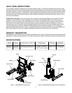
SAFETY INSTRUCTIONS (refer to Figure1 for location of components)
BEFORE USE
1. Inspect before each use. Do not use if bent, broken, leaking or cracked components are noted. Ensure the
casters and lifting arms move freely. Check and tighten any loose assemblies.
2. Verify that the product and the application are compatible, if in doubt call Blackhawk Automotive Technical Service
(816)891-6390.
3. Read, understand and follow vehicle manufacturer’s recommended tire change procedures.
4. With hydraulic unit in fully lowered position, locate and remove oil filler plug.
5. Pump 6 to 8 strokes. This will purge the hydraulic system of pressurized air trapped in reservoir. Check fluid level.
Proper level is even with filler plug hole.
6. Reinstall oil filler plug.
Figure 3 - Assembly Illustrarion for Model BH8075