Chapter 2 Service
The HP 53131A/132A Calibration Procedures
2-18 Assembly-Level Service Guide
2
To Calibrate the Gain for Channels 1 and 2
1 Press any one of the arrow keys until
CAL: GAIN 1 ?
is displayed.
2Press Enter key.
A scrolling message is displayed. Follow the instruction by performing the
following steps.
3 Connect a BNC tee connector to Channel 1 of the Counter.
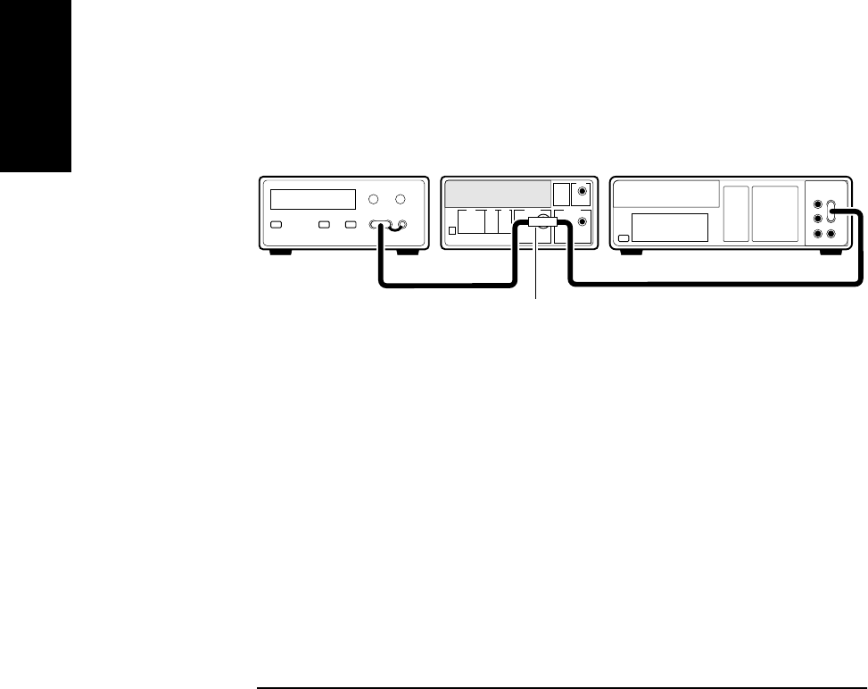
4 Connect the Counter, dc power supply, and digital multimeter as
shown in Figure 2-2.
Figure 2-2. Gain Calibration Setup
5 Adjust the power supply until the digital multimeter displays
+ 5.000 V ± 0.001 V.
6 Disconnect the digital multimeter from the Counter to prevent
noise from being introduced into the measurement.
7Press Enter key.
The Counter momentarily displays
CALIBRATING
, and then it should
display
GAIN 1 PASS
.
If the fail message is displayed, refer to the troubleshooting section in this
chapter.
+
--
DC Power Supply
HP 53131A/132A
Counter Digital Multimeter
BNC Tee


