SERVICE AND ADJUSTMENTS
TO LEVEL MOWER HOUSING
Adjust the mower while tractor is parked on level ground or •
driveway. Make sure tires are properly inflated (See "PROD-
UCT SPECIFICATIONS" section of this manual). Iftiresare
over or underinflated, you will not properly adjust your
mower.
SIDE-TO-SIDE ADJUSTMENT (See Figs. 16 and 17)
• Raise mower to its highest position.
• At the midpoint of both sides of mower, measure height
from bottom edge of mower toground. Distance"A" on
both sides of mower should be the same or within 1/4"
of each other.
• If adjustment is necessary, make adjustment on one
side of mower only.
• To raise one side of mower, tighten lift link adjustment
nut on that side.
• To lower one side of mower, loosen lift link adjustment
nut on that side.
NOTE: Three full turnsof adjustment nut witlchange mower
height about 1/8".
• Recheck measurements after adjusting.
BOTTOM EDGE BOTTOM EDGE
OF OF MOWER
MOWER
TO GR_ROU ND
V
_GROUND LINE--'-"-'-'-
FIG. 16
SUSPENSION ARM
NUT
FIG. 17
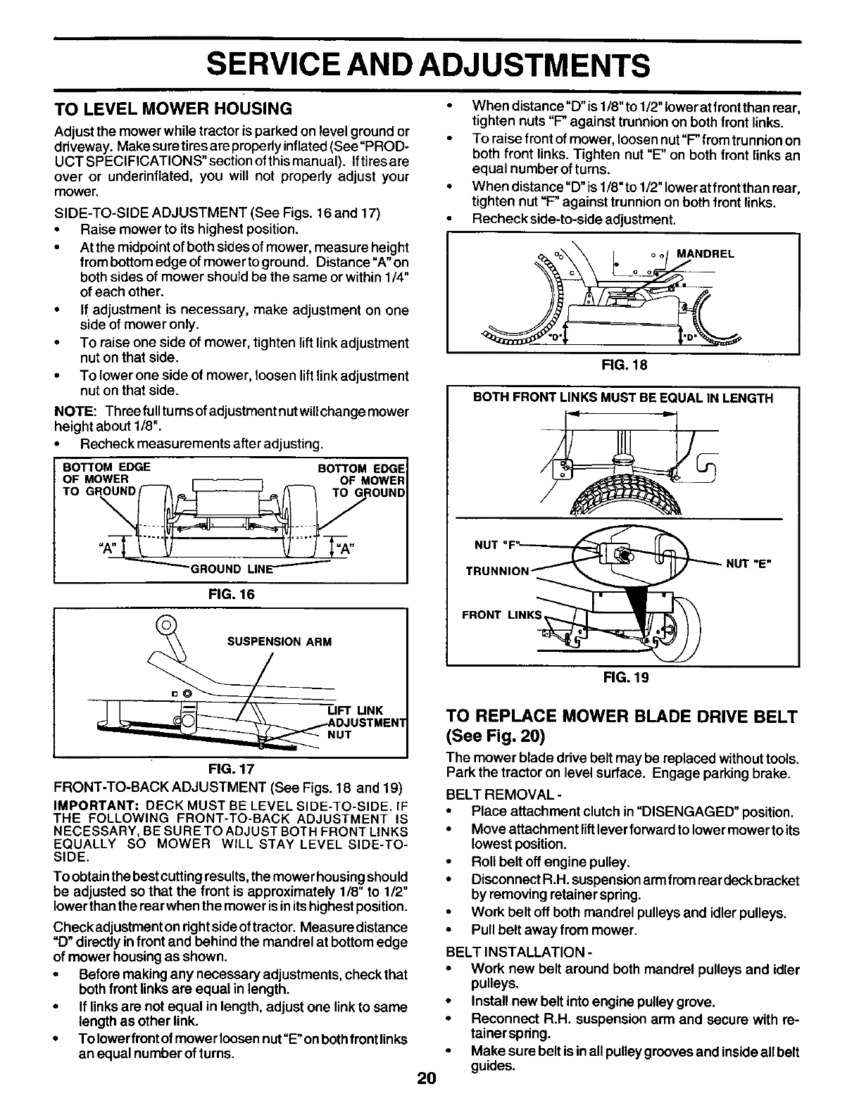
FRONT-TO-BACK ADJUSTMENT (See Figs. 18 and 19)
IMPORTANT= DECK MUST BE LEVEL SIDE-TO-SIDE. IF
THE FOLLOWING FRONT-TO-BACK ADJUSTMENT IS
NECESSARY, BE SURE TO ADJUST BOTH FRONT LINKS
EQUALLY SO MOWER WILL STAY LEVEL SIDE-TO-
SIDE.
To obtainthe best cuttingresults,the mowe r housing should
be adjusted so that the front is approximately 1/8" to 1/2"
lower than the rearwhen the mower is in its highest position.
Checkadjustment on right side of tractor. Measuredistance
"D" directly in front and behind the mandrel at bottom edge
of mower housing as shown.
• Before making any necessary adjustments, check that
both front links are equal in length.
• If links are not equal in length, adjust one link to same
length as other link.
• To lower front of mower loosen nut "E" on both front links
an equal number of turns.
When distance"D"is 1/8"to 1/2" lowerat frontthan rear,
tighten nuts "F" against trunnion on both front links.
To raise front of mower, loosen nut"F" from trunnion on
both front links. Tighten nut "E" on both front links an
equal number of turns.
When distance "D" is 1/8"to 1/2" lower at front than rear,
tighten nut "F-"against trunnion on both front links.
Recheck side-to-side adjustment.
MANDREL
20
FIG. 18
BOTH FRONT LINKS MUST BEEQUAL IN LENGTH
NUT"F___,_
TRUNNION _1_1_ _ NUT "E"
FRONT LINK__
FIG. 19
TO REPLACE MOWER BLADE DRIVE BELT
(See Fig. 20)
The mower blade drive belt may be replaced withouttools.
Park the tractor on level surface. Engage parking brake.
BELT REMOVAL -
• Place attachment clutch in"DISENGAGED" position,
• Move attachment lift lever forwardtolowermower to its
lowest position.
• Roll belt offengine pulley.
• Disconnect R.H. suspensionarm fromrear deck brecket
byremoving retainer spring.
• Work belt off bothmandrel pulleys and idler pulleys.
• Pullbelt away from mower.
BELT INSTALLATION -
• Work new belt around both mandrel pulleys and idler
pulleys.
• Install new belt into engine pulley grove.
• Reconnect R.H. suspension arm and secure with re-
tainerspdng,
• Make sure belt is inall pulleygroovesand insideallbelt
guides.


