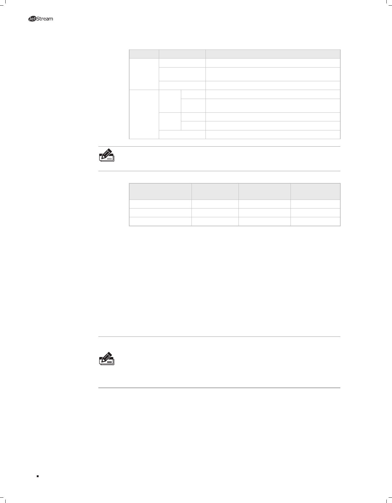
LED Status Indication
PoE Max
On The remaining PoE power≤
7W.
Flashing
The remaining PoE power keeps ≤
7W after this LED is
on for 2 minutes.
Off The remaining PoE power≥
7W.
10/100/
1000 Mbps
Green
On The port is supplying power normally.
Flashing
The supply power exceeds the correponding port's
maximum power.
Yellow
On Overload or short circuit is detected.
Flashing Power-on self-test has failed.
Off No PoE power supply is provided on the port.
Note:
TL-SG3216/TL-SG3424/TL-SG3424P switch features some
“
Combo
”
ports. A
“
Combo
”
port consists of a RJ45 port and a SFP port, and the two ports share the
same LED.
Port Feature
Model
10/100/1000Mbps
RJ45 Port
Console Port SFP Port
TL-SG3210 8 1 2
TL-SG3216 16 1 2
TL-SG3424/TL-SG3424P 24 1 4
10/100/1000Mbps Port
Designed to connect to the device with a bandwidth of 10Mbps, 100Mbps or
1000Mbps. Each has a corresponding 1000Mbps LED.
Console Port
Designed to connect with the serial port of a computer or terminal for monitoring
and configuring the switch.
SFP Port
Designed to install the SFP module. TL-SG3216/TL-SG3424/TL-SG3424P switch
features some SFP transceiver slots that are shared with the associated RJ45 ports.
The associated two ports are referred as a
“
Combo
”
port, which means they cannot
be used simultaneously, otherwise only SFP port works.
TL-SG3210 features two
individual SFP ports.
Note:
For TL-SG3216/TL-SG3424/TL-SG3424P, when using the SFP port with a
100M module or a gigabit module, you need log on to the GUI (Graphical User
Interface) of the switch and congure its corresponding Speed and Duplex mode on
Switching
→
Port
→
Port Cong page. For 100M module, please select 100MFD while
select 1000MFD for gigabit module. By default, the Speed and Duplex mode of SFP port
is 1000MFD. TL-SG3210 supports 1000M SFP module connection only.
Rear Panel
■
The rear panel of TL-SG3210 is shown as the following figure.
Introduction


