Page 6 / NORSEMAN™ 1500/2500 FURNACE VGZ-018 / 0805.1
LOCATING FURNACE
NOTICE: Installation of this furnace must be done
by a qualified heating equipment installer.
C A U T I O N : F U R N A C E U N I T S A R E
HEAVY - APPROXIMATELY 450-550 LBS.
MAKE SURE YOU HAVE PROPER EQUIP-
MENT AND OR SUFFICIENT MANPOWER TO
PREVENT INJURY WHEN DELIVERING AND
LOCATING FURNACE UNITS.
1. The furnace must be placed on solid concrete or
masonry floor. NOTE: To reduce weight during in-
stallation remove parts from inside the firebox.
Additional weight reductions can be obtained
by removing the fire brick. Make note of position
so they are returned to the same positions.
CAUTION: DO NOT OPERATE THIS APPLIANCE
WITH CRACKED OR MISSING FIREBRICKS.
2. The furnace should be located in the same
room as the central heating system, as close as
possible but no closer than 6˝ to the central system.
(See figures 16 – 23)
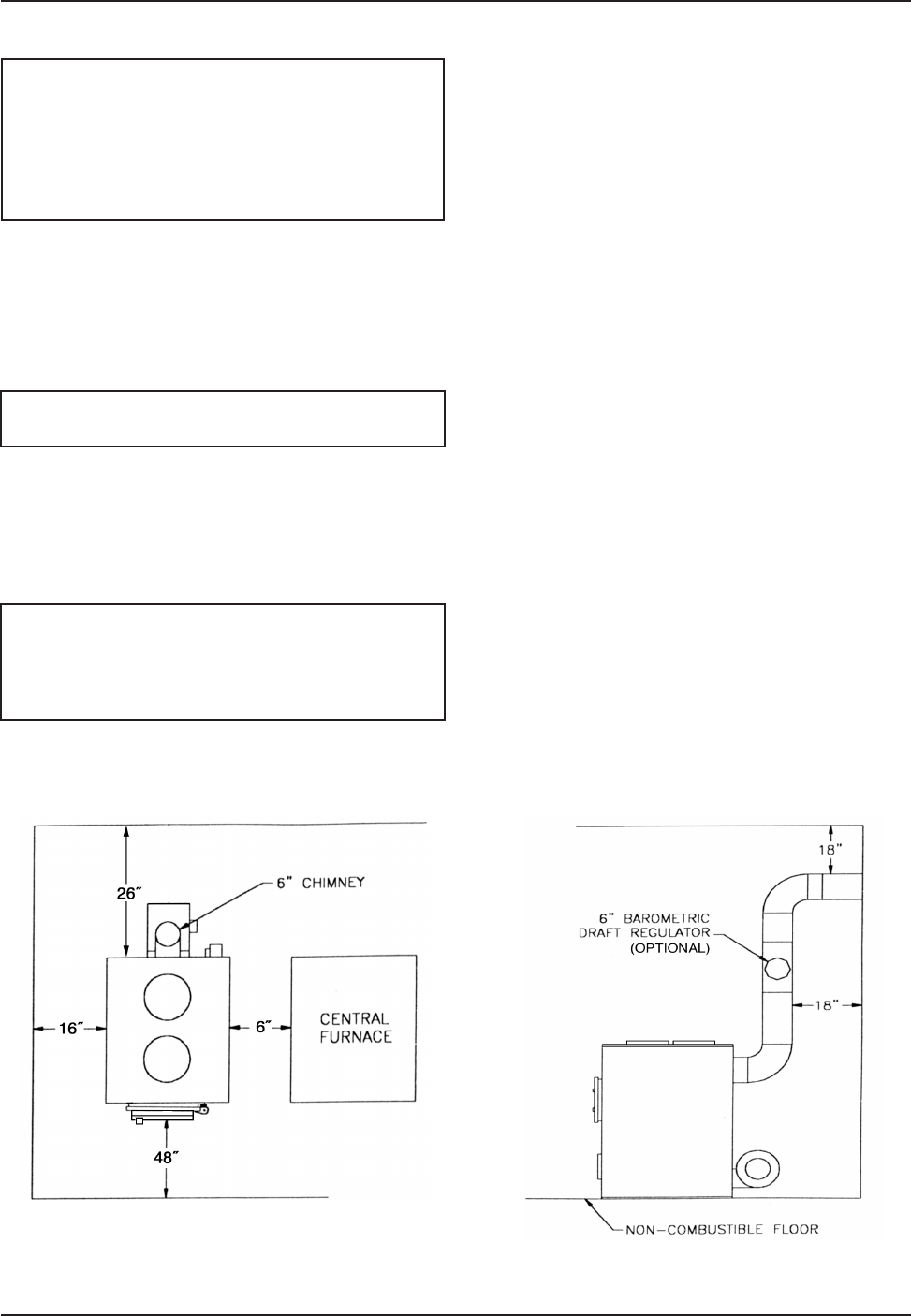
3. Obser ve the clearances to combustible
materials as listed and shown in figures 1, 2 & 3.
Minimum Clearances to Combustible Surfaces
Front: 48 in. Side: 16 in. Back: 26 in.
Chimney Connectors: 18 in. Plenum to wall-
studs, joists or finished wall or ceiling: 2 in.
4. The furnace must have its own flue. DO NOT CON-
NECT THIS UNIT TO A CHIMNEY FLUE SERVING
OTHER APPLIANCES.
5. Install furnace pipe, elbows, and thimble as
required, utilizing either a recently cleaned and
inspected 6˝ masonry chimney or a 6˝ i.d. listed UL
103 HT chimney. NOTE: A barometric draft regula-
tor may be necessary if the chimney draft is found
to be excessive
6. Us e 6˝ rou nd bl ack f ur na ce p ipe , n ot
galvanized furnace pipe. Secure pipe sections with
three (3) sheet metal screws in each furnace pipe
and/or elbow joint to firmly hold the pipe sections
together.
7. Re che ck c lea ran ces fro m t he f ur na ce,
connector furnace pipe, and corner clearanc-
es using the illustrations in figures 1 – 3 and
your local building codes or fire protection
ordinances.
NOTE: A studded wall faced with brick or stone
should be considered a combustible surface.
8. DO NOT INSTALL THIS FURNACE IN A MOBILE
HOME, MANUFACTURED HOME, TENT OR TRAILER.
NO EXCEPTIONS! (HUD Federal Standard: 24 CFR Ch.XX)
9. The clearances provided are minimum dimen-
sions determined by the manufacturer’s test-
ing facility in accordance with U.S. Test Stan-
dard UL 391. Installation of this furnace must
comply with the latest edition of NFPA 211 for re-
duced clearances and/or your local building code
rulings (use whichever minimum dimensions are
LARGEST).
Fig. 1 – TOP VIEW
Minimum Clearances from Combustible Surfaces
Fig. 2 – SIDE VIEW
Minimum Clearances from Combustible Surfaces


