Chapter 2 Hardware Installation and Connections
IES-5106M / IES-5112M / IES-6000M User’s Guide
31
2.3.3 Installing a Splitter Chassis Card
The splitter card’s type and slot must match those of the line card to which it is to
connect. For example, install ASC1024 cards in the slots below an ALC line card in
the main chassis (see Figure 34 on page 42). Use the SEC1024 extension card
with the VOP1248G VoIP line card. Leave the slot covers on unused splitter slots.
Use the following procedure to install a splitter or extension card in the splitter
chassis.
1 If there is one splitter chassis below the main IES main chassis, install a line card’s
splitter or extension cards below the line card and in adjacent slots (a
management switch card does not need a splitter chassis card).
If there are two splitter chassis below the main IES main chassis, install the
splitter or extension cards in the splitter chassis slots that correspond to the slot
number of the line card in the main chassis.
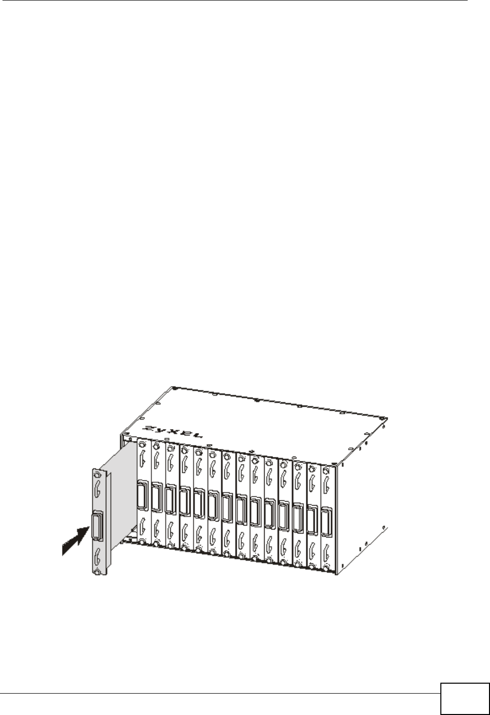
2 Grasp the center of the front panel of the card with one hand and place the other
hand under the card to support it.
3 Insert the card into the slot and push it in until the front panel of the card is flush
with the front panel of the splitter chassis.
4 Tighten the two thumbscrews.
Figure 24 Installing a Splitter Chassis Card


