Page 9
)LJXUH)
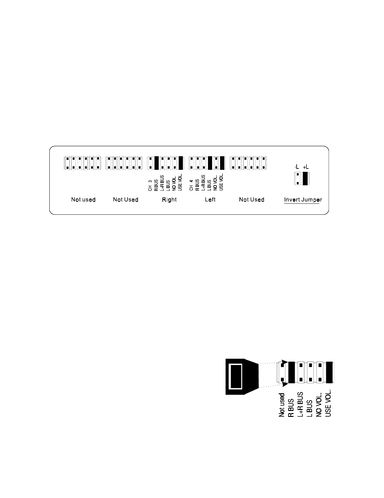
)LJXUH*
ST260’s internal bus structure
In order to
ain access to the internal bus structure,
ou must first remove the top cover.
Turn the amplifier so the rear panel is facin
our. The jumper modules ma
be seen
on the circuit board just behind the level controls.
Below is the default setup for the ST260 amplifier. B
arran
in
the jumpers allows
ou
to confi
ure the amplifier for different applications. If
ou wish to use the amplifier as a
stereo (two channel) amplifier,
ou need not chan
e an
of the settin
s.
In order to reconfi
ure the ST260’s channels, remove the source control
roup jumper
from its present position (if necessar
) and install it on the terminal
ou wish to select as
the source for that channel. Make sure it has been inserted on both terminal pins of the
jumper modules.
To complete the confi
uration, the volume
roup jumper should be placed at either the
‘USE VOL’ or ‘NO VOL’ terminal dependin
on
ou confi
uration.
Note: A channel that is not bein
used in your confi
uration should have its jumper plu
s
installed at the default position as shown in Fi
ure F.
Jumper description
Fi
ure G illustrates the jumper modules used in
confi
urin
each channel. Each jumper terminal
location is convenientl
labeled as to the source it
can be confi
ured to provide. Explained further on
the followin
pa
e.


