Operation
This section of the manual discusses the operation of a PVS 405D device.
Topics covered include:
• Front Panel Overview
• Configuration
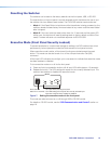
• Resetting the Switcher
• Front Panel Lockout (Executive Modes)
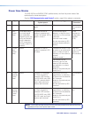
• Power Save Modes
• Setting Up and Optimizing the Audio
Front Panel Overview
PVS 405D
POLEVAULT SWITCHER
AUDIO LEVEL ADJUSTINPUTS
1
2
SELECT
CONFIG
R
PEAK
NORMAL
SIGNAL
INPUT
3
4
5
AUX
AUDIO
PEAK
NORMAL
SIGNAL
VOICELIFT
PAGING
SENSOR
SENSITIVITY
3
9
84
2
1
11
10 13126
5
7
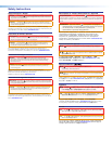
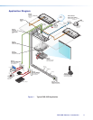
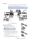
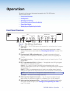
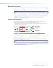
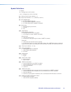
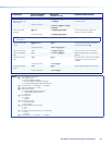
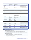
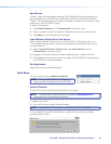
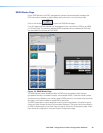
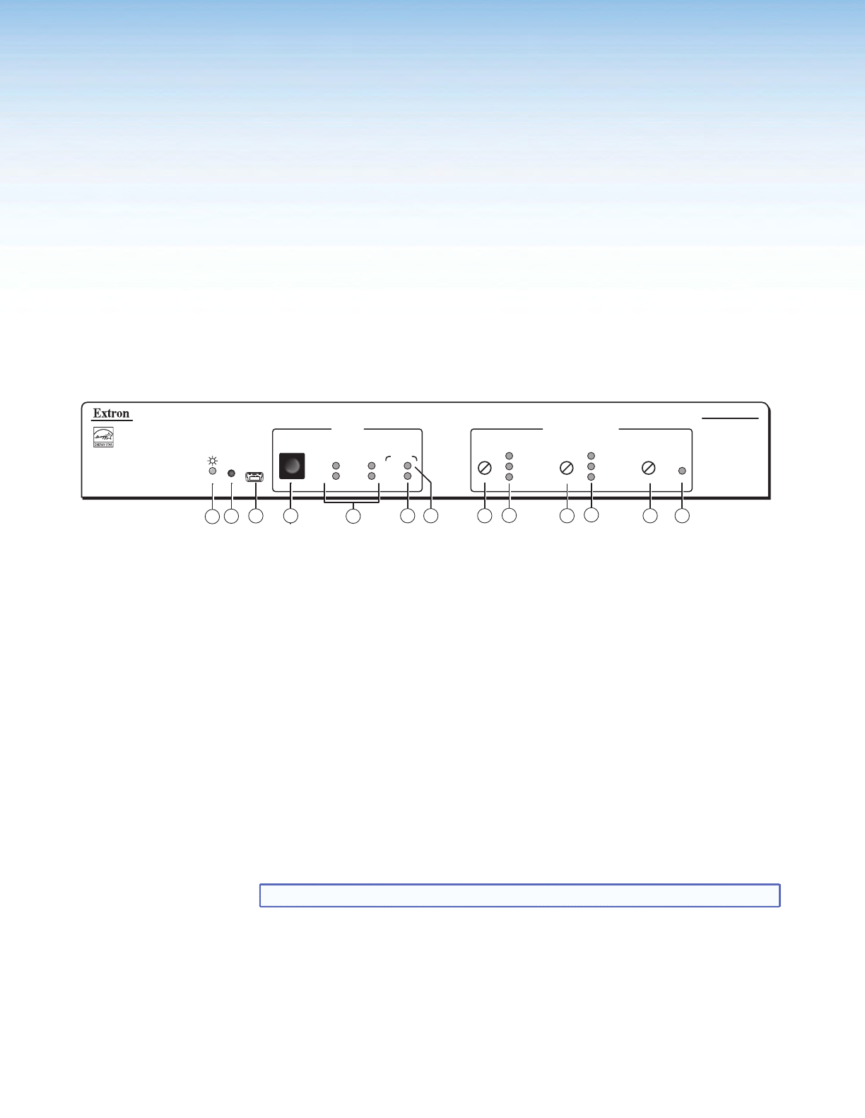
Figure 6. PVS 405D Front Panel Features
a Status LED — This LED lights green when powered up, and amber when in power
save mode.
b Device Reset button — Pressing this inset button resets the switcher to default
settings. There are two reset modes. See “Resetting the Switcher” on page 10 for
details.
c Front panel mini USB configuration port — Connect a computer to this mini
USB port (cable not supplied), for device configuration, control, and upgrading the
firmware.
d
Input selection button — Pressing this toggles through and selects inputs 1‑5 and
the Aux input.
e f g Input selection LEDs (1-4, 5, Aux) — The applicable input LED lights green
when that input is selected and active.
Inputs 1 - 4 — Inputs 1 through 4 are HDMI with embbedded audio, or high
resolution RGB signals input via the PVT wallplates. The analog RGB signal is digitized
at the wallplate.
Input 5 — Input 5 is a dedicated‑audio only input for an auxiliary, stereo, line‑level
analog audio signal from an output source such as an iPod device or an MP3 player.
NOTE: Input 5 is audio only. No video signals are supported on this input.
Aux Input — This input is mono analog audio only.
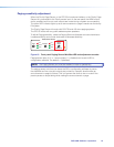
h Audio input level adjustment encoder — Use this encoder to adjust the input
levels through 43 positions per rotation in 1 dB steps (‑18 to +24 dB, default 0).
i Audio input level adjustment LEDs — These three LEDs indicate the active audio
level (peak, normal and signal). See ”Setting Up and Optimizing the Audio” on
page 12 for details.
PVS 405D Switcher • Operation 8