18
920-087-02 (9-03)
Appendix A (continued)
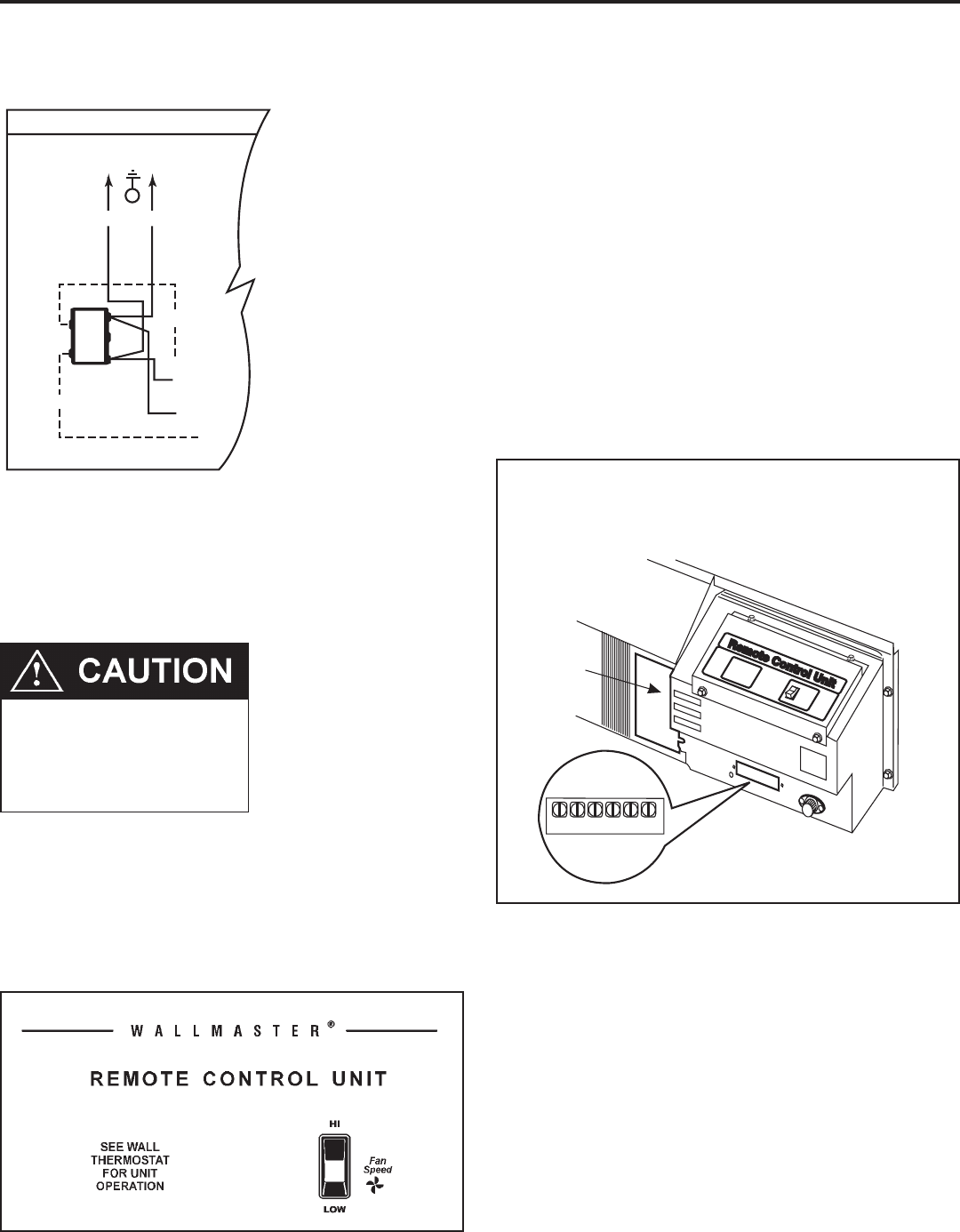
The simplified connection diagram at left shows the factory
congured wiring set for 240V operation. If you are going to use
208V exclusively, switch the two (2) black wires on the 240V post
of the primary side of the transformer to the 208V post. This will
ensure correct secondary (low) voltages for the unit. This is only
required on remote thermostat units.
Remote Thermostat 208V Operation
Remote Thermostat Unit Operation
These units are controlled by the use of a remote thermostat that will
cycle the unit to maintain desired room temperature. See thermostat
operating instruction sheet for details.
The fan speed switch controls high and low speed fan operation. It is
located on the control panel and is independent of the thermostat.
Auto Changeover Thermostat
A single stage heat/cool thermostat with auto changeover is needed.
The wiring scheme is the same as the manual thermostat.
Connection Diagram
208V
60HZ
L2 L1
SMOOTH RIBBED
G
240V
208V
24V
COM
RED
R
Y
BK
SECONDARY
TRANSFORMER
PRIMAR
Y
Remote Thermostat Installation
Follow Steps 1 through 5 (pages 12 and 13), then:
6. Locate the terminal strip on the front of the control box (See
Figure 9). Attach the thermostat subbase wires (eld supplied)
to the appropriately labeled terminals in accordance with the
wiring diagram on the side of the chassis.
7. Carefully route the wires alongside the conduit or service cord.
Attach the other end of the wires to the appropriate terminals
on the thermostat subbase. See the thermostat directions for
proper wiring and mounting of the thermostat.
Terminal Strip Location
Figure 10
Remote Contr
ol Unit
Remote Contr
ol Unit
OFF
ON
C W Y R G B
CAUTION
If the supply voltage is 208V, the low
voltage transformer MUST be wired for
208V operation. Failure to do so will result
in lower control voltages to the unit and can
damage low voltage components.


