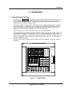
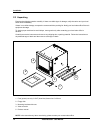
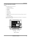
Installation
Video Recorder - User Manual 22
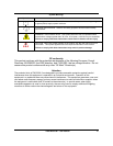
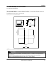
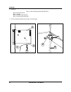
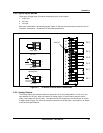
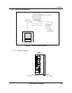
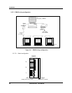
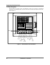
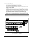
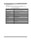
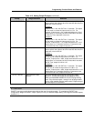
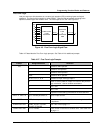
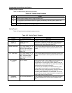
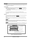
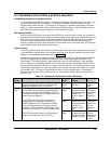
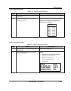
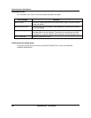
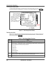
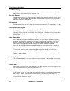
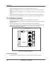
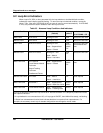
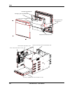
2.5.3 Analog input boards
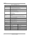
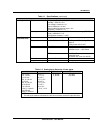
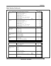
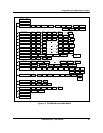
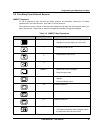
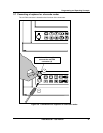
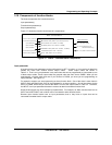
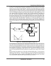
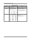
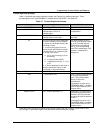
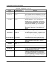
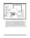
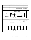
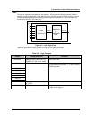
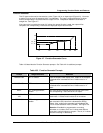
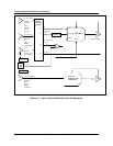
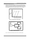
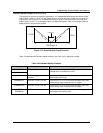
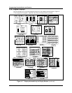
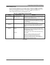
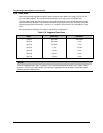
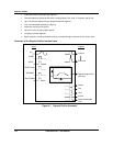
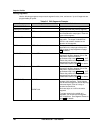
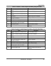
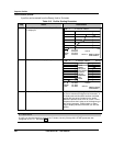
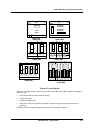
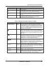
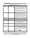
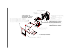
A universal Analog Input board accepts a variety of input signals from field devices.
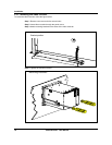
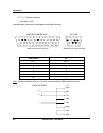
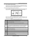
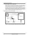
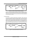
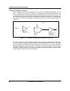
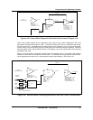
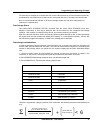
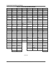
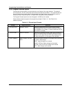
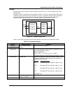
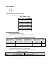
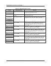
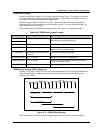
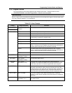
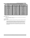
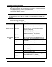
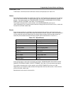
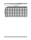
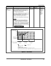
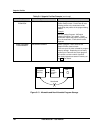
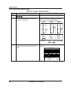
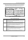
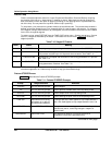
Figure 2-1 illustrates the terminal block connections for the various inputs. One AI board can be
configured to accept multiple input types.
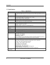
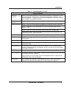
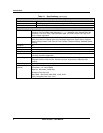
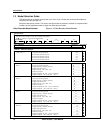
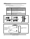
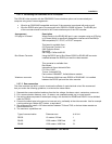
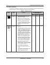
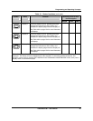
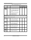
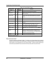
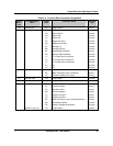
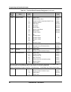
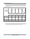
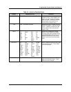
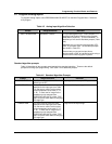
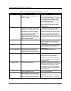
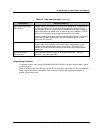
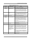
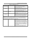
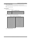
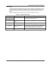
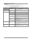
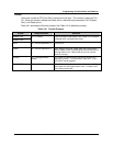
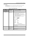
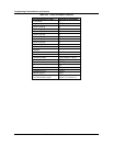
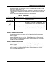
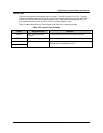
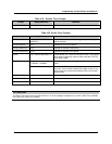
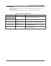
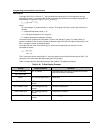
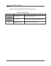
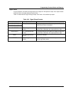
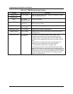
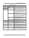
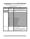
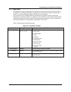
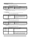
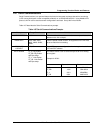
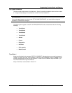
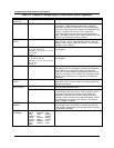
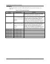
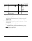
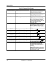
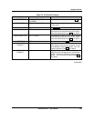
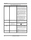
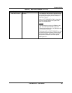
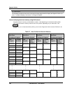
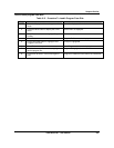
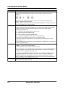
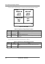
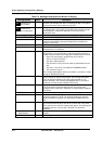
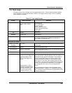
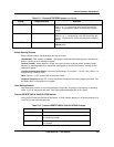
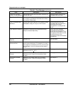
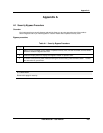
Table 2-1 Universal Analog Input Board Specifications
Specification Description
Input Types mV, V, mA, T/C, RTD, and Ohms
Number of Inputs 4 per board, up to 12 boards per video recorder (48 inputs)
Signal Source Thermocouple with cold junction compensation, for operation
between 0 to 80º C (32 to 176º F)
Line resistance up to 1000 ohms, T/C, mV, mA, V
RTD, 3-wire connections, 40 ohms balanced max.
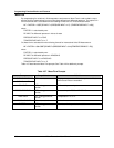
Input Impedance
10 Meg Ω for T/C, mV inputs,
> 1 Meg Ω for volt inputs
+
-
T/C, mV, V
+
-
*
4 to 20
mA
Source
12
11
10
9
8
7
6
5
4
3
2
1
1
Channel 4
Channel 3
Channel 2
Channel 1
+
-
+
-
+
-
RTD
+
-
RTD
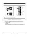
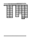
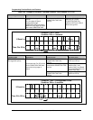
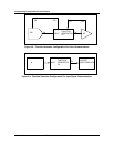
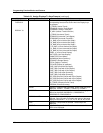
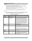
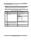
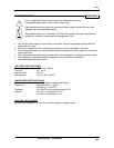
Therm ocouple input
Ground Terminal
RTD Input (3 wires)
+
-
RTD
Current Input m A
*
A 250 ohm resistor is required for the
input range
Ground Terminal
mV, V
Inputs
+
-
mV or V
source
G round Term inal G round Term inal
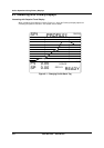
Slot ID
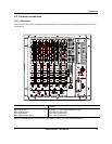
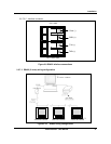
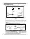
Figure 2-1 AI Board Terminal Block Connections
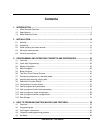
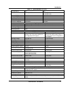
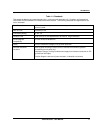
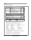
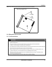
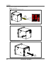
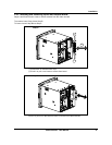
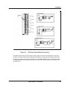
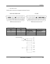
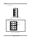
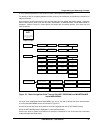
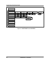
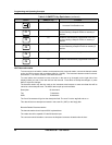
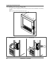
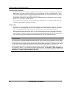
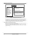
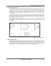
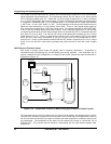
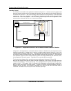
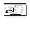
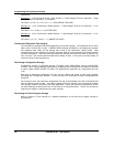
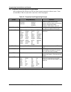
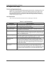
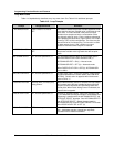
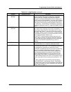
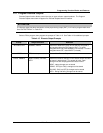
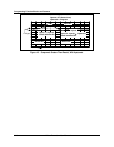
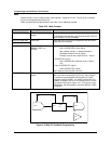
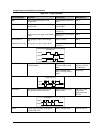
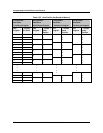
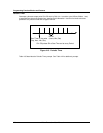
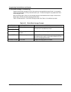
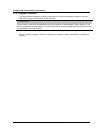
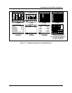
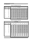
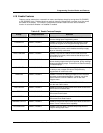
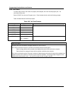
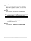
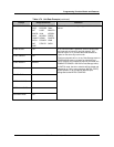
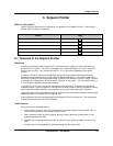
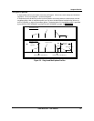
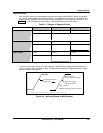
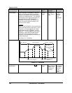
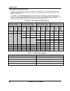
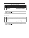
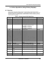
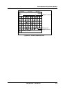
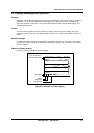
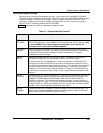
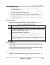
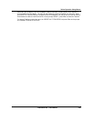
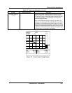
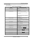
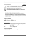
Figure 2-2 10 ohm Copper connections
-
+
RTD
-
+
RTD
10 ohm Copper
with common
round lead
Grounded lead of
RTD should be
connected to RTD
terminal of VRX
terminal block
All RTD connections are
common on Universal AI
board.