Page 7 of 21 Rev: 1/21/2014 7:15 AM
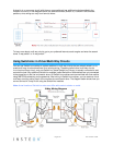
• Notice that the red traveler wires are not used, so they are capped off at both ends with wire nuts
o The black traveler wire (traveler 2) is converted to a line wire
o In SwitchLinc Secondary wall box, connect traveler 2 to the existing line wire and to
SwitchLinc Secondary line wire
o In the wall box at the other end of the circuit, connect traveler 2 to SwitchLinc Primary line
wire
• The SwitchLinc Primary load wire is connected to the actual lights being controlled
• The load wires on all SwitchLinc Secondaries will not be connected to anything, so cap them off
with wire nuts
• All SwitchLinc modules—Primary and Secondaries—must be connected to neutral and ground
o SwitchLinc will not function without a neutral
o The switches you are replacing usually will not have a neutral connection
o If there is no neutral wire in the wall box, consult an electrician or call the INSTEON
Support line at 1-800-762-7845
Installing Multi-Way SwitchLinc Modules
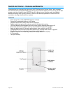
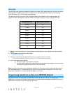
When replacing a 3-way mechanical switch, each switch will have three wires connected to it from the
wall box. Four- or more-way circuits will have four wires connected to the switches in the center of the
circuit. For this tutorial, we will follow the most commonly used wire colors for North American homes:
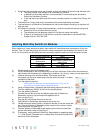
Line wire (also called hot)
Ground wire
Bare copper, green wire or
green screw
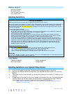
1) Disable power at the circuit breaker panel
2) Pull all the switches in the multi-way circuit out of their wall boxes. Each switch should have at
least three wires connected to it, depending on whether it is a 3-way, 4-way or more-way circuit.
3) Unscrew the wires from the old switches. If the wires cannot be
unscrewed, cut the wires where they enter the switch and strip ½” of bare
insulation off the ends.
4) Turn the electricity back on
Make sure the wires are not touching anything. They are not
grounded and could cause an electrical shock.
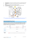
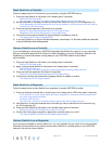
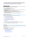
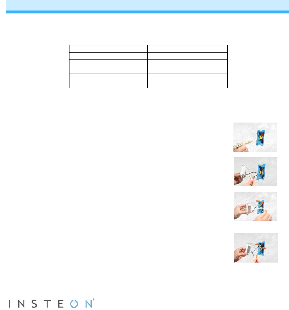
5) Using a voltage meter, individually test and identify each wire (see Fig. 1)
The wire measuring 120VAC is the line wire (usually black)
6) Turn the electricity back off
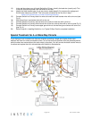
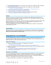
7) Connect the wall box line wire and black traveler wire to SwitchLinc
Secondary line wire. Cap all three wires together with a
wire nut (see Fig. 2).
8) Cap wall box red traveler wire with a wire nut
9) Cap SwitchLinc Secondary red load wire with a wire nut
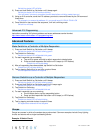
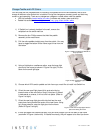
10) Locate the neutral wires (usually a white wire bundle) in the rear of the wall
box. Connect SwitchLinc Secondary white neutral wire to the box neutral
wires with a wire nut (see Fig. 3)
11) Connect SwitchLinc Secondary bare copper ground wire to the wall box
ground wires with a wire nut (see Fig. 4)
12) If necessary, install additional SwitchLinc Secondaries by repeating steps
7-11. See Special Treatment for 4- or More-Way Circuits at the end of this
section for more information.