10
Pelican Water Systems
877-842-1635, www.pelicanwater.com
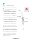
Feed and Drain Connec on
Feed Connec on
1. Locate and turn off the angle stop valve on the cold water line feeding the sink. This valve will
usually be located under the sink on the pipe coming out of the wall.
2. When the angle stop valve is closed, relieve pressure in the line by opening the cold water tap
on the sink.
3. Disconnect the cold water faucet feed line at the angle stop valve.
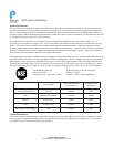
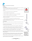
4. Install the feed adapter into the angle stop. (Fig. 1)
5. Firmly press the green 1/4” tubing into the 1/4" connector on the feed adapter.
6. Connect the cold water faucet feed line into the feed adapter.
7. Make sure the small shut-off valve on the green feed line is closed. Turn on the feed water con-
nec on valve. Check for leaks.
7. A ach the small feed valve warning tag from the parts bag to the feed valve.
8. A ach the Shutoff Warning label to the system so that it is directly visible. Fill out the Date of
Installa on label and a ach to the side of the system.
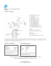
Drain Connec on
1. You will need an electric drill with a 3/8” bit and a screwdriver for this por on of the installa-
on.
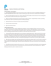
2. Obtain the drain saddle assembly, two 1 ½” bolts, two 3/8” hex nuts, and the small adhesive
foam pad from the small parts bag (Fig. 2).
3. Place the adhesive foam pad on the inside of the the drain saddle front, aligning the holes.
4. Posi on the drain saddle on the drain pipe under the sink between the “P” trap and the sink
connec on. Orient the drain saddle so that the opening is on the side of the drain pipe.
5. Using the bolts and hex nuts, hand ghten the saddle bracket evenly un l the saddle grips the
pipe snugly. Use a Phillips screwdriver to fully ghten the bolts. Do not over ghten.
6. If necessary, remove the drain saddle connector nut from the opening of the drain saddle. Us-
ing the connector opening in the side of the drain saddle as a guide, drill a 3/8" hole through the
wall of the drain pipe.
7. Extend the drain tubing from the RO dispensing faucet to the drain saddle and measure for
length. The tubing must be routed so that water can run downhill for the en re length of the
tubing from the faucet. Avoid low spots or loops. Cut the tubing shorter, if necessary.
8. Insert the drain tube from the R.O. dispensing faucet through the drain saddle connector nut.
Tighten the connector nut onto the drain saddle.
Fig. 2
Fig. 1
Note: The drain saddle
assembly must be
installed before the
'P' trap. Do not install
the drain saddle
assembly between the
'P' trap and the wall.
Installa on Videos
www.youtube.com/
pelicanwatertech