2.3 Appearance Description
2.3.1 Front Panel
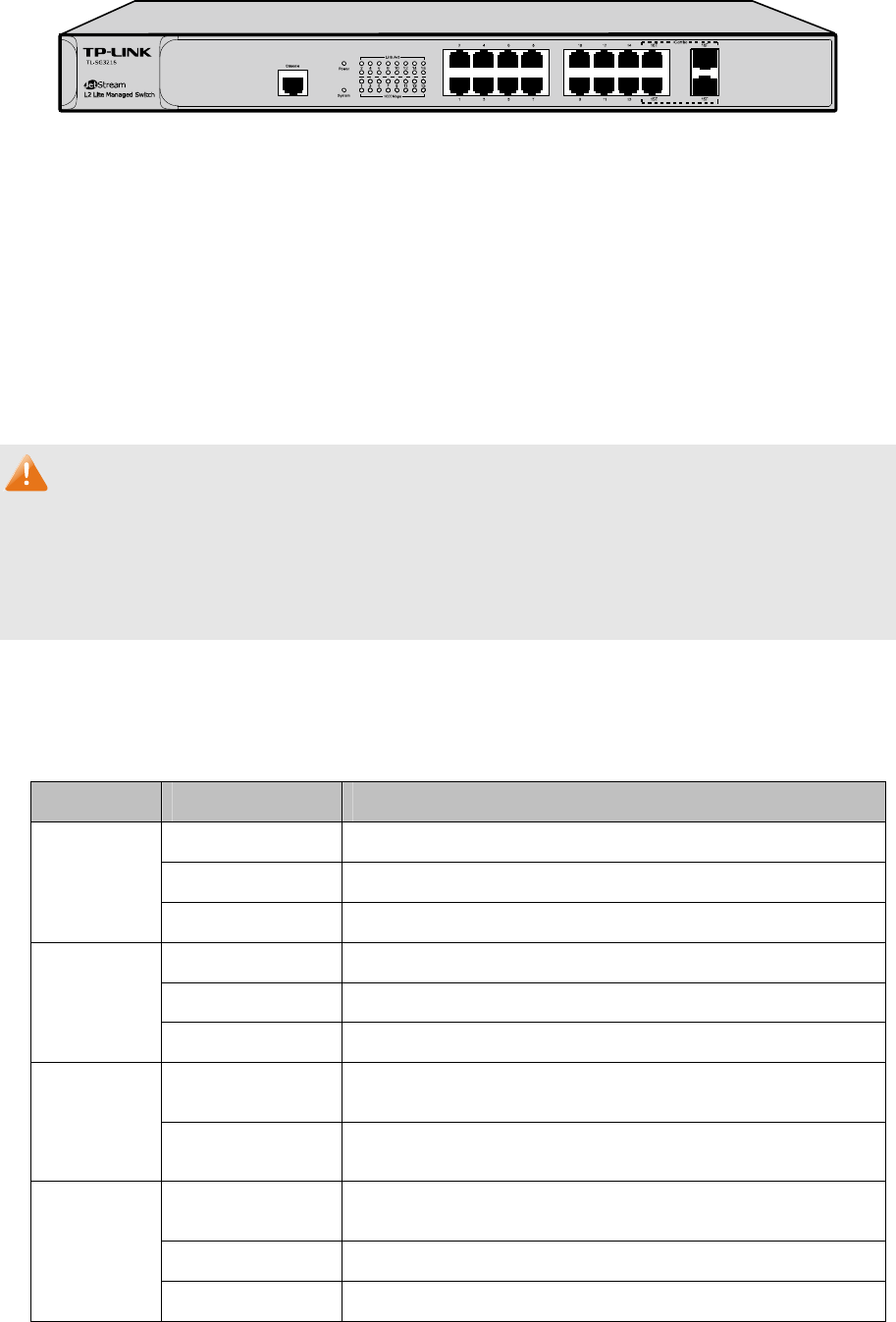
Figure 2-1 Front Panel
The following parts are located on the front panel of the Switch:
¾ 10/100/1000Mbps Ports: Designed to connect to the device with a bandwidth of 10Mbps,
100Mbps or 1000Mbps. Each has a corresponding 1000Mbps LED.
¾ SFP Ports: Designed to install the SFP module. Port 15F shares the same LED with Port 15T
and Port 16F shares the same LED with Port 16T. The Port 15F (16F) and Port 15T (16T) are
referred to as “combo” ports, which means they cannot be used simultaneously, otherwise only
SFP ports work.
Note:
When using the SFP port with a 100M module or a gigabit module, you need to configure its
corresponding Speed and Duplex mode on Switching→Port→Port Config page. For 100M
module, please select 100MFD while select 1000MFD for gigabit module. By default, the Speed
and Duplex mode of SFP port is 1000MFD.
¾ Console Port: Designed to connect with the serial port of a computer or terminal for monitoring
and configuring the Switch.
¾ LEDs
Name Status Indication
On Power is on.
Flashing Power supply is abnormal.
Power
Off Power is off or power supply is abnormal.
On The Switch is working abnormally.
Flashing The Switch is working normally.
System
Off The Switch is working abnormally.
On
A 1000Mbps device is connected to the corresponding
port.
1000Mbps
Off
A 10/100Mbps device or no device is connected to the
corresponding port.
On
A device is connected to the corresponding port, but not
activity.
Flashing Data is being transmitted or received.
Link/Act
Off No device is connected to the corresponding port.
7


