7
1
2
N(L2)
N(L2)
GROUND
GROUND
L(L1)
L(L1)
ACC.SLOT
RS-232
ARALLEL
EPO
SW
ACC.SLOT
RS-232
PA LLEL
EPO
SW
CAUTION:
CAUTION:
DO NOT DISCONNECT DO NOT DISCONNECT
1
2
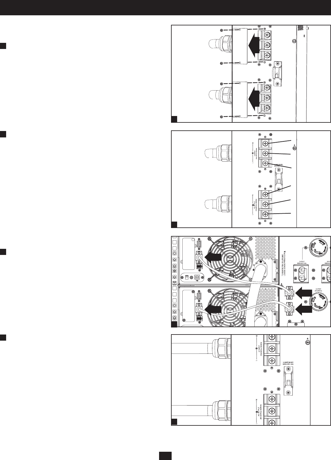
Connection continued
Terminal Wiring Connections
SUPDMB20KHW
1
Unscrew the 2 screws to remove the Input and Output Terminal
Access covers.
2
Connect the 2 sets of N (L2), Ground and L (L1) wires (1 Input,
1 Output) according to markings on the connectors as seen in the
diagram below. Be sure to connect one set of wires to the input
terminals and the other set to the output terminals.
Parallel Connection
1
Being sure that all switches are off and all units are powered down,
connect the 2 parallel cables. Both will originate from the parallel
PDU with 1 connecting to the primary power module and the other
to the secondary power module. (Refer to the diagram.)
Ensure that each of the parallel cables is securely attached
to the PDU and UPS by tightening the thumbscrews on each
connection.
2
Connect the input (SUPDMB20K & SUPDMB20KIEC), and/or
hardwired input/output (SUPDMB20KHW) AC power connections
located on the PDU. The AC input cord attaches to the facility’s
AC source while the AC output cord connects to the intended
equipment.


