Effective April, 1999
IL 33-DB6-1
Page 15
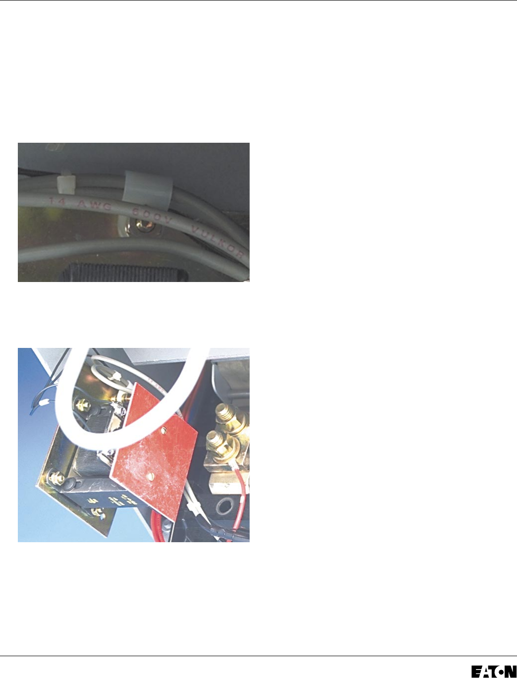
H. Secure the Load Side HV Wires to the left
inside of the Breaker by sliding the supplied
nylon wire clamp over the wires then installing
the wire clamp on the .190-32 x 1.00" screw
used to mount the front of the CPT Assembly.
Use the (1) .190" flat washer, (1) lock washer,
and (1) nut supplied to secure the wire clamp
to the screw.
I. Secure the insulation plate to the top of the
CPT Assembly, as shown, using the (2)
.138-16 x .375" thread cutting screws supplied.
NOTE: The power convention of the DB-25
Breaker is normally Top to Bottom, meaning
the Top Breaker Stabs are on the Line Side
of the Breaker and the Bottom Breaker
Stabs are on the Load Side.
The HV Wires from the CPT MUST BE
ATTACHED to the Line Side of the Breaker. If
it is determined that the power flow for the
Breaker application is opposite the normal
convention, the HV Wires must be attached
to the Bottom Breaker Stabs.
J. Route the HV Line Side Wires up through
rubber grommet installed in the rear Breaker
Frame in Step 9-C, then up towards the Phase
1 and 2, or Phase 2 and 3 Top Breaker Stabs.
NOTE: The Line Side HV Wires are longer
than necessary and are cut during the
following steps. Before cutting the wires, be
sure that sufficient length is left so that the
HV Wire Fuses are accessible from the front
of the Breaker and that the connections can
be made to the correct Breaker Stabs.
K. Secure the Line Side HV Wires to the right
inside of the Breaker using the existing hole and
the (1) nylon wire clamp, (1) 190-32 x .625"
screw, (1) extra wide flat washer, (1) flat washer,
(1) lock washer, and (1) nut supplied.


