Effective April, 1999
IL 33-DB6-1
Page 18
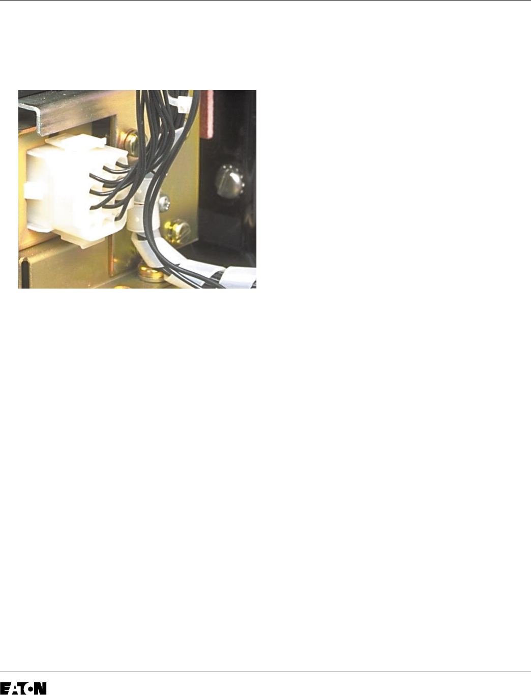
C. Secure the External Harness to the right side
of the Aux. CT Module using the existing
holes and the (2) nylon wire clamps and (2)
.138-32 x .375" threading cutting screws.
D.
For Kits Supplied with an Auxiliary Switch Only.
Connect the External Harness to the Auxiliary
Switch by routing the two (2) wires (with ring
terminals) from the External Harness, along the
right Breaker Frame, down to the DTA
Assembly. Connect one wire to the normally
“Open” terminal of the Auxiliary Switch and the
other wire to the “Common” terminal.
E.
For Kits Supplied with a Breaker Mounted
CPT Only.
Remove the External Harness plug
installed in the Trip Unit. Insert the black plug of
the CPT Harness into the same receptacle in
the Trip Unit. Reinsert the External Harness
Plug just removed into the female receptacle on
the CPT Harness.
F. Use nylon wire ties provided to secure all wires
and harnesses away from any moving parts
within the Breaker.
Step 12: Testing the Breaker
A. Measure the force necessary to trip the Breaker
at the point where the Trip Finger contacts the
adjusting screw. The force necessary to trip the
Breaker MUST NOT EXCEED 3 lbs.
B. The Retrofit must be tested using primary
injection. Refer to Section 8 of the
Instructions
for the Application of Digitrip RMS Retrofit Kits
on Power Circuit Breakers
(Publication
AD-33-855-1, June 1997), supplied with the
Retrofit Kit, for detailed testing procedures and
specifications. For test information specific to
the Trip Unit, refer to the IL publication supplied
with the Retrofit Kit (see the Pick List for the IL
number).
C. While Section 8 of the Instructions for the
Application of Digitrip RMS Retrofit Kits on
Power Circuit Breakers provides the information
necessary for testing the Breaker, please keep
the following notes in mind when reviewing
other sections of the publication.
Caution: When all testing is complete, the Trip
Unit must be reset. Failure to do so may cause
the Battery in the Rating Plug to run down.
Notes:
1. Publication AD-33-855 was created
specifically for the “hundred” series
(500, 600, 700, etc.) Retrofit Kits. Therefore
certain sections and figures do not apply to
the “ten” series (510, 610, 810, etc.) Retrofit
Kits. Specifically, these are Sections 13 and
14, as well as Figures 3-2, 3-3, and 3-4.
2.
For All Kits Other Than 510 Basic.
If testing
the Breaker with Short Delay or Ground
Fault functions, be sure to either plug in the
Cell Harness Assembly or use the Zone
Interlock Shorting Plug. Failure to do so may
result in shorter than expected trip times.


