Effective April, 1999
IL 33-DB6-1
Page 4
Step 2: Removing the Original Components
Refer to the Westinghouse DB-25 Instruction
Manual, originally supplied with the Breaker, to
perform the following procedures.
A. Remove the bottom Finger Clusters and
set them aside for installation later in the
Retrofit process.
For Breakers Equipped with the Original
Electromechanical Trip Units.
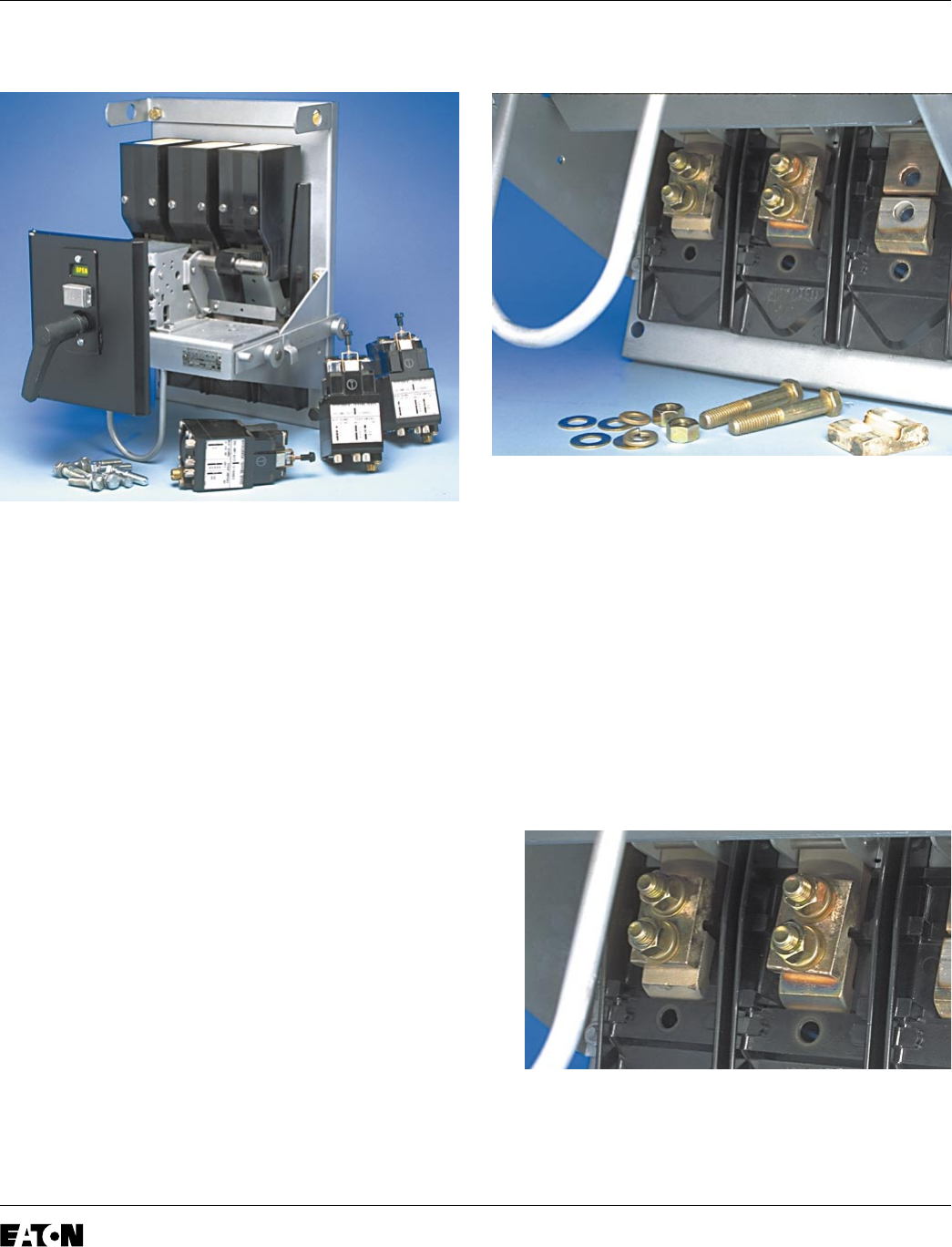
B. Remove the two (2) .500-13 bolts directly
above each of the three bottom Breaker Stabs.
As the bolts are removed, the original
Electromechanical Trip Units will drop free.
Scrap the Trip Units and all mounting hardware.
C. Remove and scrap the three (3)
Electromechanical Trip Paddles from the
Breaker Trip Bar. This will reduce the force
required to trip the Breaker.
For Breakers Equipped with an Amptector or
Other Trip System.
D. Remove and scrap the Trip Mechanisms and
all associated wiring, mounting brackets
and hardware.
Step 3: Installing the Copper Connectors
A. Install a .500" flat washer on each of the (6)
.500-13 x 3.00" bolts supplied. Working from the
rear of the Breaker, insert the bolts into the
holes from which the original Electromechanical
Trip Unit mounting hardware was removed.
B. Working from the bottom front of the Breaker,
install a copper connector on each set of .500"
bolts. The Copper Connectors must be installed
with the flat side facing the front of the Breaker
and the thicker end towards the top of the
Breaker. Secure the Copper Connectors using
the (6) flat washers, (6) lock washers, and (6)
nuts supplied.
For Kits Supplied with a PT Module Only.
Do not tighten the three bottom nuts at this time.
They will be used to connect the PT Wires later
in the Retrofit Process


