B. Remove the nut, flat washer, and spring from
the Reset Assembly Post. Slide the post
through the hole on the Reset Arm. Reinstall
the hardware in the same order in which it was
removed.
C. Apply Loc-Tite
®
242 to the threads of the three
.250-20 × .750" screws provided. Align the DTA
Platform Assembly with the holes drilled in
Step A. Using the screws, flat washers, lock
washers, and hex nuts provided, mount the
DTA Platform Assembly to the left Breaker
Side Plate as shown.
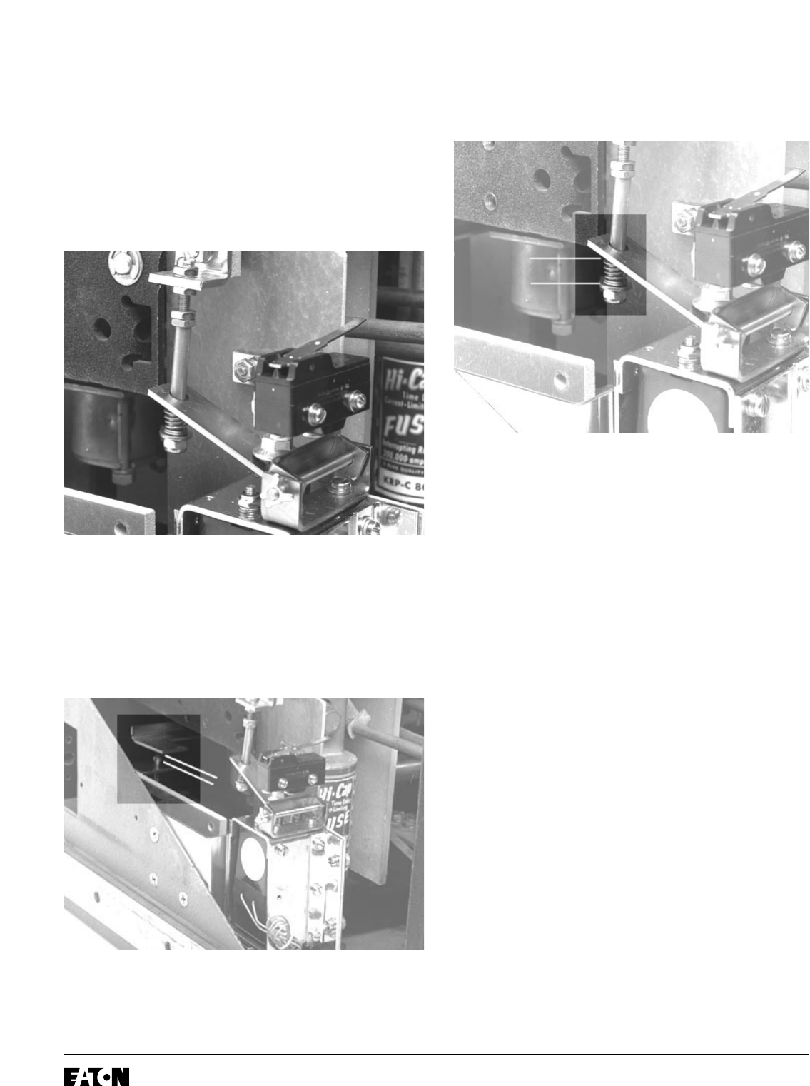
D. With the Breaker in the “Open” position, set
the gap between the Trip Finger and the Gap
Adjusting Screw at .06".
E. Again with the Breaker in the “Open” position,
set the height of the Reset Spring to .50" ± .06.
To increase the Reset Spring height, loosen
the top lock nut on the Reset Shaft. Move the
adjusting nut up until the desired height is
obtained. Re-tighten the lock nuts. If the lock
nut on the bottom of the Reset Shaft is all the
way to the bottom and the desired Reset
Spring height can still not be obtained, back off
on the flange nut on the DTA Shaft.
To decrease the Reset Spring height, loosen
the bottom lock nut on the Reset Shaft. Move
the adjusting nut down until the desired height
is obtained. Re-tighten the lock nuts.
F. Connect a 24V DC power supply to the DTA
terminals: positive to positive and negative to
negative. Close the Breaker manually. Energize
the DTA to trip the Breaker: de-energize when
the Breaker trips. Repeat the procedure several
times to insure that the trip and reset functions
are working properly.
Effective December, 1998
IL 33-FC6-1
Page 10
SPRING
HEIGHT
GAP