18 Issue 1, December 2003 61223424L2-5A
7. HDSL4 DEPLOYMENT GUIDELINES
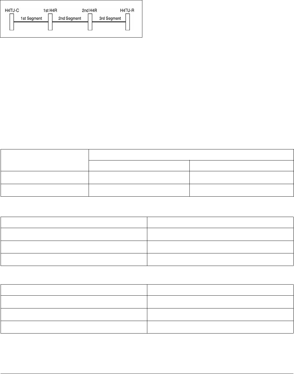
The different segments of an HDSL4 circuit are defined
in Figure 26.
Figure 26. HDSL4 Circuit Segments
The ADTRAN HDSL4 system provides DS1-based
services over loops designed to comply with the guide-
lines given below. These guidelines apply to the
following circuit configurations:
• a single segment or an HDSL4 circuit with no
H4Rs,
• a circuit having two segments (with one H4R), or
• a circuit having three segments (with two H4Rs).
The guidelines reflected herein are for worst-case
scenarios, that is, for loops that contain a maximum
amount of disturbers, noise, etc. Actual deployment
guidelines may vary based on local policy. Please refer
to those guidelines on an as-necessary basis to ensure
optimum performance.
Designing a circuit with loop attenuation greater than
the recommended maximum loss may result in compro-
mised reliability of that loop. Follow the guidelines in
in this section to ensure that the circuit meets basic
requirements:
1. All loops are nonloaded only.
2. Any single bridged tap is limited to 2 kft.
3. Total bridged tap length is limited to 2.5 kft.
4. Bridge tap within 1000 feet of units may affect
performance of the circuit.
5. Loop Attenuation Limits. See Table 6.
6. DSL-Recommended Range Limits. See Table 7
and Table 8.
Table 6. Attenuation limits
Recommended Maximum
Upstream Downstream
1
st
segment
30 dB 32 dB
2
nd
and 3
rd
segment
28 dB 28 dB
Table 7. Range Limits: 26 Gauge / 70°F / PIC
26 Gauge Recommended Maximum
1
st
segment
10,470 ft.
2
nd
segment
9,865 ft.
3
rd
segment
9,865 ft.
Table 8. Range Limits: 24 Gauge / 70°F / PIC
26 Gauge Recommended Maximum
1
st
segment
14,770 ft.
2
nd
segment
14,050 ft.
3
rd
segment
14,050 ft.


