61223424L2-5A Issue 1, December 2003 5
3. CONNECTIONS
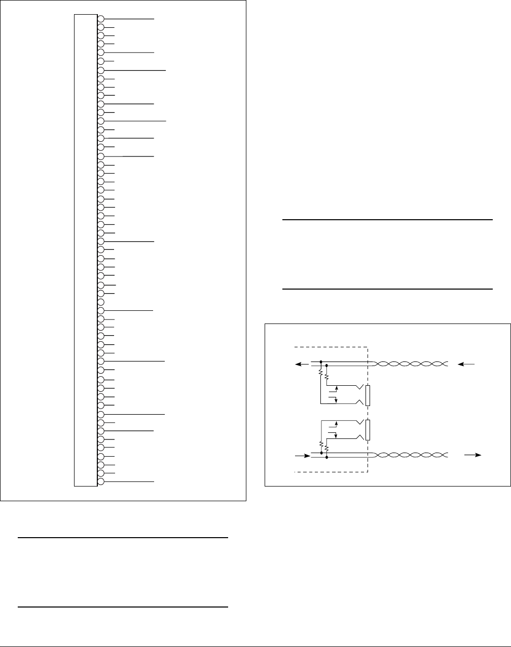
All connections of the T200 H4TU-R are made through
card edge connectors. Figure 2 gives the card edge pin
assignments for the T200 H4TU-R circuit pack.
Figure 2. H4TU-R Edge Connector Wiring
CAUTION
Ensure chassis ground is properly connected
for either standalone or shelf-mounted applica-
tions.
4. HDSL4 SYSTEM TESTING
The T200 H4TU-R provides diagnostic, loopback, and
signal monitoring capabilities.
The seven front panel LEDs provide diagnostics for
HDSL4 loops, DS1 signals, alarms, provisioning, and
loopbacks. Refer to the Installation section for details.
The H4TU-R provides a bidirectional loopback via the
loopback button on the front panel. Refer to the
H4TU-R Network Loopbacks and Customer Loopbacks
sections for more details.
DS1 MON Bantam Jacks
The MON jack provides a non intrusive access point for
monitoring the characteristics of the transmit and
receive signals at the DS1 interface point.
For example, the DS1 MON jack on the H4TU-R could
be used to connect to a bit error rate tester to monitor for
synchronization, test patterns, etc.
Figure 3 is an illustration of specific jack detail.
NOTE
For the MON jacks, the TX and RX indications
relate to the direction of the signal to/from the
CPE.
Figure 3. H4TU-R MON Diagram
1
2
3
4
5
6
7
8
9
10
11
12
13
14
15
16
17
18
19
20
21
22
23
24
25
26
27
28
29
30
31
32
33
34
35
36
37
38
39
40
41
42
43
44
45
46
47
48
49
50
51
52
53
54
55
Chassis Ground
HDSL4 Ring Loop 1
Chassis Ground
DS1 RX Ring
HDSL4 Tip Loop 2
HDSL4 Ring Loop 2
DS1 RX Tip
DS1 TX Ring
HDSL4 Tip Loop 1
–24 V/-48 V Return
–24 VDC/-48 VDC
DS1 TX Tip
RX
TX
DS1
MON
CPE
DS1
INTERFACE
H4TU-R
T
R
T1
R1


