DISASSEMBLY AND ASSEMBLY
Rev. B
3-4
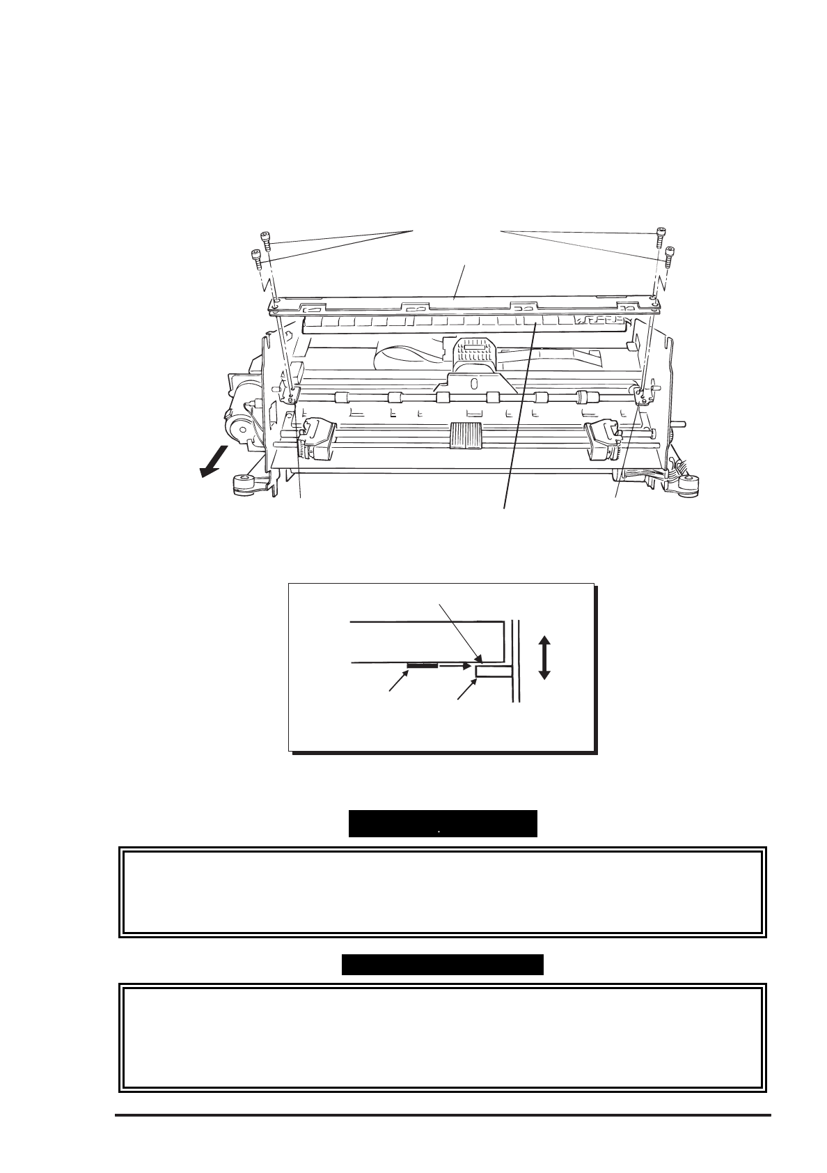
3.2.6.10 Platen Removal
Step 1: Remove the paper bail assembly. (Refer to Section 3.2.6.7.)
Step 2: Remove the upper paper guide. (Refer to Section 3.2.6.8.)
Step 3: Remove the four hexagon socket screws securing the platen to the platen holders. Then remove
the platen with the lower paper guide composed of 3 parts in it.
Step 4: Slide the 3 parts of the lower paper guide to release the notches and remove them one by one
from the platen.
H exagon Socket Screw
Platen
Platen Holder (Left)
Platen Holder (R ight)
Low er Paper G uide
R ear
Figure 3-62. Platen Removal
Platen
Platen Holder
Positionning Tab
0 .0 3 m m
Thickness G auge
Front
R ear
No through
Figure 3-63. Platen Positioning
ASSEMBLING POINT
• When you attach the 3 parts of the lower paper guide to the platen, start with the one at the right end
and work toward the left.
• When you mount the platen to the platen holders, space between the platen and positioning tab on
the both sides must be less than 0.03mm. (Refer to Figure 3-63.)
ADJUSTMENT REQUIRED
When you install the platen, perform the following adjustments:
• Carriage guide shaft parallelism adjustment (described in Section 4.1.5 and Section 4.1.6)
• Platen angle (right angle) adjustment (described in Section 4.1.6)
• Platen gap motor value (platen gap) adjustment (described in Section 4.1.7)


